The logic of finite automata operation
State Machines It is an abstract model of computation that sequentially transitions between different states based on input data or events. A finite state machine includes two approaches to model construction — a state machine and a transition graph.
Logic of the state machine
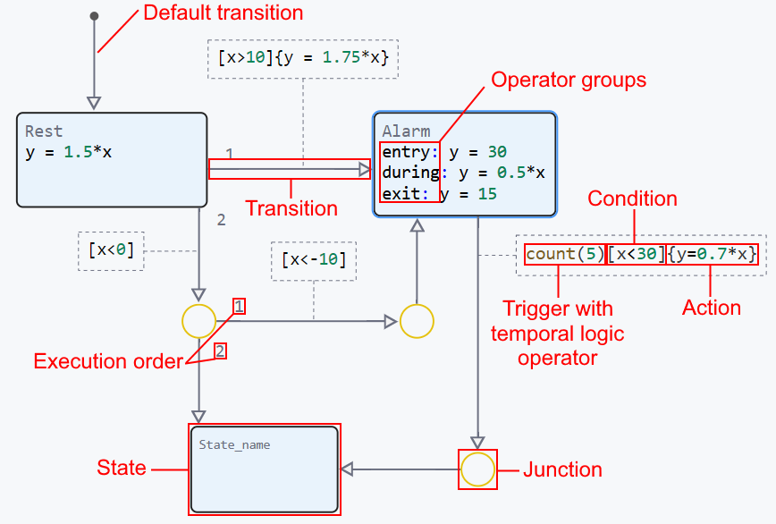
State Machines It is a representation of an event—driven system that switches from one mode of operation to another when the condition determining the change is true. State machines use all available block functionality Chart to build models of a finite automaton, namely:
-
and everything related to them.


An example of a finite state machine with a state machine:
The execution algorithm consists of the following steps:
The general logic of the state machine
-
The operation of the state machine begins before any state is activated.:
-
1. If the state machine has a default transition (or several such transitions), then actions related to these transitions are performed first, taking into account their priorities and conditions.;
-
2. If there are several transitions by default, the transitions are analyzed in the order of the set priorities until a transition with an incomplete or missing condition is detected, after which the corresponding state is activated.;
-
3. If there are no default transitions and there is a single state, then it is activated automatically.
Go to point 2.
-
-
At the next step of the machine, after activating the state, possible transitions from the active state are checked. There can be zero, one, or several such transitions.
-
1. If there are no transitions from the current active state, the machine remains in the same current state, and the sections are executed.
duringandon(if specified) of this state. Sectionexitthis condition is never performed.
-
2. If there is only one transition from the current state, then its condition is checked. If the condition is not met, the machine remains in the same current state, and the sections are executed.
duringandon(if specified) of this state. If the condition has the value "true", then, first, the transition action is performed (if specified). Secondly:-
2.1. If the transition leads to a different state, the following steps are performed:
exitcurrent status and sectionentrya different state (if specified). Another state becomes active instead of the current one (hierarchical states are not considered here).
-
2. 2. If the transition leads to the same state (here we are considering only external transitions), sections are executed
exitandentrythe current state, and it remains active.
-
2.3. If the transition leads to a dead end node, then the current state remains active, and its sections are executed.
duringandon(if specified).
-
-
3. If several transitions exit the current state, the machine tries to go through them in turn in the order of set priorities until it encounters a transition whose condition is fulfilled or absent (composite transitions are not considered here — see the next paragraph). If there is no such transition, then the machine remains in its current state, and the sections are executed.
duringandon(if specified) of this state. If the transition is found, then see paragraphs 2.2.1, 2.2.2 and 2.2.3.
-
-
If any of the transitions (clauses 2.2 and 2.3) is composite (consists of two or more segments) and has forks, the backtrackingfootnote mechanism can be implemented:[Backtracking is a problem—solving method based on an attempt to sequentially iterate through all possible solutions in order to find the right one. When the program reaches a decision node (for example, in the transition graph, it may be an exit node), and all possible options for further actions turn out to be incorrect (for example, all transitions from the node have false conditions), it returns (backtracks) to the previous decision node and tries another (alternative) option.]: moving through the transitions according to their priorities and conditions, the automaton remembers the passed forks, and if the condition of the next transition is not fulfilled, the automaton returns to the nearest passed fork, where alternative branches have not been tested, and makes a new attempt, but along an alternative path. If there are no forks with alternative paths, then the current state remains active, and its sections are executed.
duringandon(if specified).
Groups of operators
In the state machine groups of operators entry, during and exit initiates the execution of actions when states change and while being in the state. The logic of executing these operators is closely related to transitions, states, and activation order. Let’s take a closer look at how each group of operators works and how they interact with each other.:
-
Checking transition conditions — At each step, the state machine checks whether there is an active transition from the current state. The transition may be conditioned by conditions change indicators (
hasChangedetc.) or temporal logic (afterand others), which indicate when the transition can be made.; -
Making a transition if the condition is met:
-
If the transition conditions are met, the state machine deactivates the current state.;
-
exit— is executed before the end of the current state, if a group of operatorsexitspecified. It completes all actions related to this state.; -
Then there is a transition to a new state where a group of operators is executed.
entryfor this condition.
-
-
If the transition does not occur:
-
If the transition conditions are not met, the state machine remains in the current state.;
-
during— executed if the status is active and the actions are specified forduring. This continues at each step as long as the automaton remains in this state and the transition conditions are not met.; -
on— executed when a certain condition occurs, if the current state is active and a group of operatorsonit is related to this condition.
-
The priority of executing groups of operators
-
Transition condition — is checked first to determine whether the transition will be completed;
-
Actions on the transition — are performed after checking the condition, if the transition is confirmed;
-
exit— completes the execution of the current state before the transition; -
on— executed if the state is active and the specified event has occurred; -
entry— it is performed when a new state is activated, preparing it for performing actions; -
during— it is performed at each step of the machine, while the current state remains active.
Then the logic of the finite state machine with transitions and groups of operators is as follows:
-
At each step, the state machine checks the transition conditions. If the transition is possible, then the following actions are performed:
exitfor the current state, and thenentryfor a new one; -
If the transition does not occur, then the following actions are performed:
duringfor the current state; -
onadds the ability to respond to events by activating actions only if these events occur in the active state.
The logic of transition graphs
Transition graphs — it is a graphical construct representing the flow of operations or logic in the system. Unlike state machines, transition graphs are constructed using nodes., transitions and default transitions, not using states. An example of a finite state machine with a transition graph:
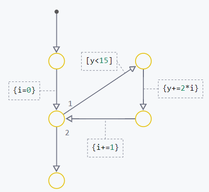
The logic of transition graphs consists of sequential analysis of nodes and transitions, starting with the default transition. The algorithm of operation can be divided into the following points:
-
Unlike a state machine, the transition graph is fully checked at each step. The transition is performed if the condition is true, or, if there is no condition, it is performed by default. If a transition is possible (the condition is true or not), then the graph performs actions related to the transition. Go to point 2.
-
When performing a transition, if the condition is true or missing, then the actions defined on this transition are performed. After that, the transition is performed to the next node specified in the graph. Completing the actions completes the second step and leads to step 3.
-
If the machine has arrived at the node, then the following actions are performed, depending on three possible outcomes:
-
1. The node is a dead end. If backtracking is possible, then it is performed. Otherwise, the automaton step is completed.
-
2. One transition originates from the node. The machine is trying to make this transition. If the condition is met, the automaton performs a transition action and proceeds to the node to which this transition leads. If the condition is not met, the machine tries to perform backtracking. If backtracking is possible, then backtracking is performed. Otherwise, the automaton step is completed.
-
3. There are several transitions coming from the node. If the automaton is at this node for the first time (within the current step), then it tries to perform the transition with the first sequence number. At the same time, the number of the transition that the machine tried to perform is remembered. If the path starting from this transition leads to backtracking, and the machine returns to the current fork, it will try to perform the next transition in order (numbered "2", then "3", etc.) until it has exhausted all available transitions or completes one of them successfully.
-
-
If the transition from the node is completed, the automaton moves to the next node and continues execution from point 1. If the transition from the node is not completed, and backtracking is possible, then backtracking is performed. If backtracking is not possible, then the automaton step is completed. The entire logic of execution is based solely on transitions between nodes, as well as memorizing and sequentially checking the sequence numbers of transitions in fork nodes.
Nodes
Knot They are the key elements of transition graphs that serve as junction points for transitions. They define the points through which the transitions pass, organizing an ordered sequence of steps in the model.
Default transitions
Default transition is a special type of transition, it does not have an initial node or state and is performed before they are activated. The system automatically adds a default transition for the first state and adds a node for the transition. The default transition is not needed if there is only one state in the system.
Transitions
Transition They represent connections between nodes that define the logic of transition from one node to another. Each transition can have a condition that is checked to determine whether to make the transition. Transitions can be conditional (performed only if a certain condition is true) or unconditional (always performed if they are active). If several transitions originate from a state or node, the program assigns explicit transitions to them. priorities displayed numerically (1,2,3, etc.). During simulation, transitions are checked in this order, and the first available transition with a true condition is performed.
Typical cases of transition logic:
-
Simple transitions between nodes that occur when conditions related to variables, parameters, or calculation results are met.;
-
Transitions that depend on change indicators (
hasChanged,hasChangedFrom,hasChangedTo), temporal logic operators, etc., which are executed when changing the values of certain parameters; -
The logic of backtracking, where transitions can return execution to the previous node to check alternative paths if the condition of the current transition is not met.
Conditions on the crossings
Conditions on the crossings [] They set logical expressions that determine when the transition should occur. These conditions may include comparing values, checking logical expressions, or using logical operators such as hasChanged. If the condition is true, then the transition is performed, and execution continues at the next node.
Examples of using conditions on traffic crossings:
-
The condition can check ranges of values, for example, the transition is carried out only when a certain parameter level is reached.;
-
Logical expressions can include several checks, for example, a set of conditions (
A > 5 || B < 10); -
Change indicators are used to determine whether the state of the system has changed at a certain moment.
Actions on transitions
Actions on transitions {} they determine which Julia statements will be executed on the transition. Actions on transitions allow you to control changes in the data state and ensure the implementation of the necessary logic depending on the selected route (priority of transitions).
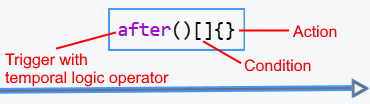
Temporal logic operators
Temporal logic operators transitions allow you to take into account time aspects or conditions related to the frequency of events. Logical operators after, at, and every (and others), set conditions for transitions based on time, repetition, or frequency of events. They can be used in a state machine within states with a group of operators. on and at the crossings.
Examples of the application of temporal logic:
-
Using the operator
afterto specify a transition that is performed after a specified period of time or the number of steps of the state machine after activating the state associated with this operator; -
Setting the transition using the operator
at, which is executed only at a given step from the moment of activation of the state associated with this operator; -
Implementation of repetitive actions using the operator
everyto set the frequency of execution.
Memory Nodes
Memory Node  allows the state machine to remember the last active child state and restore it when the parent state is reactivated. The memory node is used in situations where it is necessary to save the context of the automaton and continue execution from the same place, even after exiting and re-entering the state. The logic of the memory node is based on storing the current child state and activating it when certain conditions are met, for example, after groups are completed.
 during and on the parent state.
Examples of using a memory node:
-
Restoring the last active child state when reactivating the parent state;
-
Implementation of complex scenarios where it is necessary to temporarily exit the state and return to it while maintaining the context;
-
Managing transitions between child states based on the stored state.