PID Controller
The PID controller.
blockType: SubSystem
|
PID Controller Path in the library: |
|
Discrete PID Controller Path in the library: |

Description
Block PID Controller implements a PID controller (PID, PI, PD, only P or only I).
The output of the block is the weighted sum of the input signal, the integral of the input signal, and the derivative of the input signal. The summation weights are set by proportional, integral, and differential coefficients. The first-order pole filters the differential component.
The unit supports several types and structures of the regulator. Possible options:
-
Controller type (PID, PI, PD, only P or only I);
-
Regulator shape (parallel or perfect);
-
Time domain (continuous or discrete);
-
Initial conditions;
-
Output saturation limits and built-in anti-saturation mechanism;
-
Signal tracking for smooth control transmission and multi-circuit control.
When these parameters are changed, the internal structure of the block changes: the corresponding subsystem options are activated.
Ports
Entrance
# IN_1 — input signal
+
scalar | vector | the matrix
Details
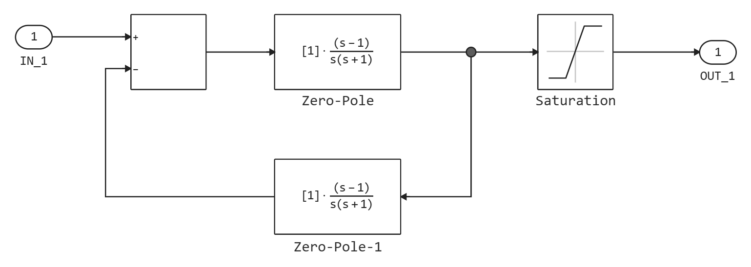
The difference between the setpoint and the output signal of the controlled system, as shown in the figure below:
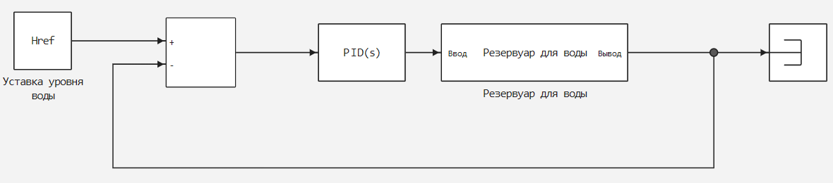
If the input signal is a vector, the block processes each signal separately, vectorizing the coefficients of the PID controller and forming a vector output signal of the same size. You can set the coefficients of the PID controller and some other parameters in the form of vectors of the same size as the input signal. This is equivalent to setting a separate PID controller for each element of the input signal.
| Типы данных |
|
| Support for complex numbers |
None |
# extTs — discrete integrator time
+
scalar
Details
The time of the discrete integrator, given as a scalar. You can use the discrete integrator’s own time value, which determines the block execution speed in Engee. The time value of the discrete integrator should correspond to the average sampling rate of external interrupts when the unit is used inside a conditionally executed subsystem.
In other words, you can set the value for any of the integrator methods below, in such a way that it corresponds to the average sampling rate of external interrupts. In discrete time, the differential term of the transfer function of the regulator is
where depends on the integration method:
-
Forward Euler: -
Backward Euler: -
Trapezoidal:
For more information about discrete integration, see description of the block Discrete-Time Integrator.
Dependencies
To use this port, set the parameter Time-domain: meaning Discrete-time and check the box PID Controller is inside conditionally executed subsystem.
| Типы данных |
|
| Support for complex numbers |
None |
# P is a proportional coefficient
+
scalar | vector
Details
The final real value of the proportional coefficient, represented by an external source in relation to the block. An external way to set the gain coefficients is useful, for example, when comparing another parameterization of the PID controller with the coefficients of the PID controller of the block. You can also use an external method for setting the gain coefficients to implement a program-enhanced PID control. In control with a programmatic change in the gain, the coefficients of the PID controller are determined using logic or other calculations in the model and fed to the block.
Dependencies
To use this port, set the parameter Source: meaning external.
| Типы данных |
|
| Support for complex numbers |
None |
# I is the integral coefficient
+
scalar | vector
Details
The final real value of the integral coefficient, represented by an external source in relation to the block. An external way to set the gain coefficients is useful, for example, when comparing another parameterization of the PID controller with the coefficients of the PID controller of the block. You can also use an external method for setting the gain coefficients to implement a program-enhanced PID control. In control with a programmatic change in the gain, the coefficients of the PID controller are determined using logic or other calculations in the model and fed to the block.
When setting the gain coefficients from the outside, changes in the integral coefficient over time are also integrated. This result arises from the way the coefficients of the PID controller are implemented inside the block. For more information, see the parameter description. Source:.
Dependencies
To use this port, set the parameter Source: meaning external.
| Типы данных |
|
| Support for complex numbers |
None |
# D is the differential coefficient
+
scalar | vector
Details
The final real value of the differential coefficient, represented by an external source in relation to the block. An external way to set the gain coefficients is useful, for example, when comparing another parameterization of the PID controller with the coefficients of the PID controller of the block. You can also use an external method for setting the gain coefficients to implement a program-enhanced PID control. In control with a programmatic change in the gain, the coefficients of the PID controller are determined using logic or other calculations in the model and fed to the block.
When setting the gain coefficients from the outside, the time changes of the differential coefficient are also differentiated. This is due to the way the coefficients of the PID controller are implemented inside the unit. For more information, see the parameter description. Source:.
Dependencies
To use this port, set the parameter Source: meaning external.
| Типы данных |
|
| Support for complex numbers |
None |
# N is the filtration coefficient of the derivative
+
scalar | vector
Details
The final real value of the filter gain represented by an external source relative to the block. An external way to set the gain coefficients is useful, for example, when comparing another parameterization of the PID controller with the coefficients of the PID controller of the block. You can also use an external method for setting the gain coefficients to implement a program-enhanced PID control. In control with a programmatic change in the gain, the coefficients of the PID controller are determined using logic or other calculations in the model and fed to the block.
Dependencies
To use this port, set the parameter Source: meaning external.
| Типы данных |
|
| Support for complex numbers |
None |
# ydot — external derivative
+
scalar | vector
Details
The derivative of the control object’s signal , supplied to the unit directly through this input port. This is useful if there is a derivative signal in the model, and you need to skip calculating the derivative inside the block.
Dependencies
To use this port, check the box Use externally sourced derivative.
| Типы данных |
|
| Support for complex numbers |
None |
# TR — tracking signal
+
scalar | vector
Details
A signal to monitor the output signal of the controller. When signal tracking is active, the difference between the tracking signal and the block output is fed back to the integrator input. Signal tracking is useful for implementing smooth control transfer in systems switching between two regulators, as well as for preventing saturation in multi-circuit control systems. For more information, see parameter description Enable tracking mode.
Dependencies
To use this port, check the box Enable tracking mode.
| Типы данных |
|
| Support for complex numbers |
None |
# UpperLimit is the upper saturation limit of the output signal
+
scalar | vector
Details
The upper limit of the block’s output signal provided by an external source relative to the block. If the weighted sum of proportional, integral and differential actions exceeds the value set on this port, the output signal of the unit is held at this value.
Dependencies
To use this parameter, in the parameter group Output saturation check the box Limit output and for the parameter Source: set the value external.
| Типы данных |
|
| Support for complex numbers |
None |
# LowerLimit is the lower saturation limit of the output signal
+
scalar | vector
Details
The lower limit of the block’s output signal provided by an external source relative to the block. If the weighted sum of proportional, integral and differential actions becomes lower than the value set on this port, the output signal of the unit is held at this value.
Dependencies
To use this parameter, in the parameter group Output saturation check the box Limit output and for the parameter Source: set the value external.
| Типы данных |
|
| Support for complex numbers |
None |
# extAW — external anti-saturation algorithm
+
scalar | vector
Details
Specify a custom overload protection algorithm on this port. The block provides two built-in methods of protection against oversaturation, however, for the disclosure of the integrator, these methods depend on whether the sum of the block components exceeds the specified limits of the output signal. If there are saturations or limitations in the model after the PID controller blocks, you can use the extAW input port to implement custom oversaturation protection logic. This block also provides a signal in front of the integrator on the preInt output port, which can be used to implement a custom algorithm.
Dependencies
To use this option, check the box Limit output in the parameter group Output saturation and for the parameter Anti-windup Method: set the value external.
| Типы данных |
|
| Support for complex numbers |
None |
Output
# OUT_1 — regulator output
+
scalar | vector
Details
The output of the controller, which is a weighted sum of the input signal, the integral of the input signal and the derivative of the input signal. The summation weights are set by proportional, integral, and differential coefficients. Which terms are involved in the summation depends on the value of the parameter. Controller:. Other parameters change the output of the block, such as the saturation limits set by the parameters Upper limit: and Lower limit:.
The output of the controller is a vector signal if the input is a vector signal. In this case, the block acts as independent PID controllers, where — the number of signals in the input vector.
| Типы данных |
|
| Support for complex numbers |
None |
# preInt — the signal preceding the integrator
+
scalar | vector
Details
The port of the output signal preceding the integrator. Use this signal as an input for the custom overload protection algorithm provided on the extAW input port.
Dependencies
To use this option, check the box Limit output in the parameter group Output saturation and for the parameter Anti-windup Method: set the value external.
| Типы данных |
|
| Support for complex numbers |
None |
Parameters
Main
Main
#
Controller: —
type of regulator
PID | PI | PD | P | I
Details
Set the composition of the regulator:
-
PID— proportional, integral and differential parts. -
PI— only the proportional and integral parts. -
PD— only the proportional and differential parts. -
P— only the proportional part. -
I— only the integral part.
| Values |
|
| Default value |
|
| Program usage name |
|
| Tunable |
No |
| Evaluatable |
Yes |
#
Form: —
structure of the regulator
Ideal | Parallel
Details
Set the structure of the regulator:
-
Parallel— the output of the controller represents the sum of the proportional, integral and differential parts, independently weighted by , and accordingly. For example, for a parallel-shaped PID controller with continuous time, the transfer function has the form:For a parallel-shaped controller with discrete time, the transfer function has the form:
where are the parameters Integrator method: and Filter method: define and accordingly.
-
Ideal— proportional gain valid for the sum of all parts. For example, for an ideal-shaped PID controller with continuous time, the transfer function has the form:For an ideally shaped regulator with discrete time, the transfer function has the form:
where are the parameters Integrator method: and Filter method: define and accordingly.
| Values |
|
| Default value |
|
| Program usage name |
|
| Tunable |
No |
| Evaluatable |
Yes |
#
Time-domain: —
discrete or continuous time controller
Continuous-time | Discrete-time
Details
For the value Discrete-time It is recommended to explicitly set the calculation step for the block. See the parameter description Sample time (-1 for inherited):. When selecting a value Discrete-time The parameters are also included Integrator method: and Filter method:.
When the block PID Controller it is located in a model with synchronous state management, the value cannot be selected Continuous-time.
| Values |
|
| Default value |
|
| Program usage name |
|
| Tunable |
No |
| Evaluatable |
Yes |
Discrete-time settings
# Sample time (-1 for inherited): — the interval between the calculation steps
Details
Specify the interval between the calculation steps as a non-negative number. To inherit the calculation step, set this parameter to −1.
It is recommended to explicitly set the calculation step of the regulator, especially if it is expected that the calculation step of subsequent blocks will change. The influence of the regulator coefficients , , and depends on the calculation step. Thus, for a given set of coefficient values, changing the calculation step changes the performance of the regulator.
If you want to start a block with an externally specified or variable sampling period, set this parameter to −1 and put the block in Triggered Subsystem. Then start the subsystem at the desired sampling period.
|
Dependencies
To use this parameter, set for the parameter Time-domain: meaning Discrete-time.
| Default value |
|
| Program usage name |
|
| Tunable |
No |
| Evaluatable |
Yes |
# PID Controller is inside conditionally executed subsystem — activation of the discrete integrator time port
Details
For discrete PID controllers, activate the time port of the discrete integrator extTs to use the eigenvalue of the sampling period for the discrete integrator. To ensure accurate discrete time integration, use the extTs port to specify a scalar value. .
Dependencies
To use this parameter, set for the parameter Time-domain: meaning Discrete-time.
| Default value |
|
| Program usage name |
|
| Tunable |
No |
| Evaluatable |
Yes |
Integator and Filter methods
#
Integrator method: —
integration method in a discrete controller
Forward Euler | Backward Euler | Trapezoidal
Details
In discrete time, the integral term of the transfer function of the regulator is , where depends on the integration method:
-
Forward Euler— a straight rectangular (left) approximation:This method is best suited for small intervals between calculation steps when the Nyquist limit is large compared to the regulator’s throughput. For long sampling times, the method
Forward EulerIt can lead to instability, even in the case of discretization of a system that is stable in continuous time. -
Backward Euler— the inverse rectangular (right) approximation:The advantage of the method
Backward EulerThe problem is that discretization of a stable continuous-time system using this method always yields a stable discrete-time result. -
Trapezoidal— bilinear approximation:The advantage of the method
TrapezoidalThe problem is that discretization of a stable continuous-time system using this method always yields a stable discrete-time result. Of all the available integration methods, the methodTrapezoidalgives the closest correspondence between the properties of the frequency domain of the sampled system and the corresponding continuous-time system.
|
For methods
|
For more information about discrete integration, see description of the block Discrete-Time Integrator.
Dependencies
To use this parameter, set for the parameter Time-domain: meaning Discrete-time, and for the parameter Controller: meaning PID, PI or I.
| Values |
|
| Default value |
|
| Program usage name |
|
| Tunable |
No |
| Evaluatable |
Yes |
#
Filter method: —
a method for calculating the derivative in a discrete regulator
Forward Euler | Backward Euler | Trapezoidal
Details
In discrete time, the differential term of the transfer function of the regulator is
where depends on the integration method:
-
Forward Euler— a straight rectangular (left) approximation:This method is best suited for small intervals between calculation steps when the Nyquist limit is large compared to the regulator’s throughput. For long sampling times, the method
Forward EulerIt can lead to instability, even in the case of discretization of a system that is stable in continuous time. -
Backward Euler— the inverse rectangular (right) approximation:The advantage of the method
Backward EulerThe problem is that discretization of a stable continuous-time system using this method always yields a stable discrete-time result. -
Trapezoidal— bilinear approximation:The advantage of the method
TrapezoidalThe problem is that discretization of a stable system with continuous time using this method always gives a stable result with discrete time. Of all the available integration methods, the methodTrapezoidalgives the closest correspondence between the properties of the frequency domain of the sampled system and the corresponding continuous-time system.
For more information about discrete integration, see description of the block Discrete-Time Integrator.
Dependencies
To use this parameter, set for the parameter Time-domain: meaning Discrete-time and check the box Use filtered derivative.
| Values |
|
| Default value |
|
| Program usage name |
|
| Tunable |
No |
| Evaluatable |
Yes |
Controller parameters
#
Source: —
data source for regulator gain coefficients and filter coefficient
internal | external
Details
Activation of the external inputs for the parameters allows you to calculate the gain coefficients of the PID controller and the filter coefficients outside the block and transmit them to the block as input signals.
-
internal— set the gain coefficients of the regulator and the filter coefficient using the parameters Proportional (P):, Integral (I):, Derivative (D): and Filter coefficient (N):. -
external— Set the PID control coefficients and filter coefficient externally using the input ports P, I, D and N.
An external way to set the gain coefficients is useful, for example, when comparing another parameterization of the PID controller with the coefficients of the PID controller of the block. You can also use an external method for setting the gain coefficients to implement a program-enhanced PID control. In control with a programmatic change in the gain, the coefficients of the PID controller are determined using logic or other calculations in the model and fed to the block.
| If you use external input gain factors, avoid making them dependent on the output signal OUT_1. With this dependence, the resulting transfer function of the PID controller leads to an algebraic loop, since it is necessary to know this value in order to calculate the value of the output signal of the block. This algebraic loop is prone to instability and divergence. Instead of the output signal, try expressing the gain coefficients in terms of time and the input signal of the block. For more information about algebraic loops, see the article Algebraic loop. |
When external gain coefficients are applied, changes in the values of the integral and differential coefficients over time are integrated and differentiated, respectively. This is because in both the continuous and discrete case, gain factors are applied to the signal before integration or differentiation. For example, for a continuous PID controller with external inputs, the integration term is implemented as shown in the following figure.

There is an input signal inside the block multiplied by the integral coefficient supplied from the outside, before integration. The result is:
Thus, the gain of the integrator is included in the integral. Similarly, in the derivative part of the block, multiplication by the differential coefficient precedes differentiation, which leads to differentiation of the gain coefficient of the derivative. .
| Values |
|
| Default value |
|
| Program usage name |
|
| Tunable |
No |
| Evaluatable |
Yes |
# Proportional (P): — proportional coefficient
Details
The final real value of the proportional coefficient. If for the parameter Form: the value is set:
-
Parallel— proportional action does not depend on integral and derivative effects. For example, for a continuous-time parallel PID controller, the transfer function has the form:For a parallel-shaped controller with discrete time, the transfer function has the form:
where are the parameters Integrator method: and Filter method: define and accordingly.
-
Ideal— proportional coefficient applies to the sum of all parts. For example, for an ideal-shaped PID controller with continuous time, the transfer function has the form:For an ideally shaped regulator with discrete time, the transfer function has the form:
where are the parameters Integrator method: and Filter method: define and accordingly.
Dependencies
To use this parameter, set for the parameter Controller: meaning PID, PD, PI or P, and for the parameter Source: meaning internal.
| Default value |
|
| Program usage name |
|
| Tunable |
No |
| Evaluatable |
Yes |
# Integral (I): — the integral coefficient
Details
The final real value of the integral coefficient.
Dependencies
To use this parameter, set for the parameter Controller: meaning PID, PI or I, and for the parameter Source: meaning internal.
| Default value |
|
| Program usage name |
|
| Tunable |
No |
| Evaluatable |
Yes |
# Derivative (D): — The differential coefficient
Details
The final real value of the differential coefficient.
Dependencies
To use this parameter, set for the parameter Controller: meaning PID or PD, and for the parameter Source: meaning internal.
| Default value |
|
| Program usage name |
|
| Tunable |
No |
| Evaluatable |
Yes |
# Filter coefficient (N): — derivative filtration coefficient
Details
The final real value of the filter gain. The filter coefficient determines the position of the filter pole in the differential part of the block. The position of the filter pole depends on the value of the parameter Time-domain::
-
Continuous-time— the position of the pole iss = −N. -
Discrete-time— the position of the pole depends on the value of the parameter Filter method::-
Forward Euler— the position of the filter pole is -
Backward Euler— the position of the filter pole is -
Trapezoidal— the position of the filter pole is
-
The block does not support N = Inf (an ideal unfiltered derivative). If for the parameter Time-domain: the value is set Discrete-time, you can uncheck the box Use filtered derivative to remove the derivative filter.
Dependencies
To use this parameter, set for the parameter Controller: meaning PID or PD, and for the parameter Source: meaning internal.
| Default value |
|
| Program usage name |
|
| Tunable |
No |
| Evaluatable |
Yes |
# Use I*Ts (optimal for codegen) — using the integral coefficient multiplied by the sampling period
Details
For discrete regulators with an integral effect, the unit takes the integral gain as an input and internally multiplies it by the sampling period during the integration process. If you check this box, it will explicitly set the integral gain multiplied by the sampling period. This reduces the amount of internal calculations and is useful if you need to improve the execution time of the generated code.
For continuous regulators, activation of this parameter does not affect the integral gain.
Dependencies
To use this parameter, set for the parameter Controller: meaning PID, PI or I.
| Default value |
|
| Program usage name |
|
| Tunable |
No |
| Evaluatable |
Yes |
# Use externally sourced derivative — specify the derivative on the input port of the block
Details
Select this checkbox to specify the derivative of the control object’s signal. directly through the input port ydot. This is useful if there is a derivative signal in the model, and you need to skip calculating the derivative inside the block.
Dependencies
To use this parameter, set for the parameter Controller: meaning PID or PD.
| Default value |
|
| Program usage name |
|
| Tunable |
No |
| Evaluatable |
Yes |
# Use filtered derivative — applying a filter to a derivative
Details
For discrete-time PID controllers only: uncheck this box to replace the filtered derivative with an unfiltered value. In this case, the differential term of the transfer function of the regulator will be equal to
For continuous-time PID controllers, the derivative component is always filtered.
Dependencies
To use this parameter, set for the parameter Time-domain: meaning Discrete-time, and for the parameter Controller: meaning PID or PD.
| Default value |
|
| Program usage name |
|
| Tunable |
No |
| Evaluatable |
Yes |
Initialization
Integrator and Filter initial conditions
# Integrator: — the initial condition of the integrator
Details
The initial condition of the integrator, used to initialize the integrator at the beginning of the simulation.
The initial condition of the integrator cannot be NaN or Inf.
Dependencies
To use this parameter, set for the parameter Controller: meaning PID, PI or I.
| Default value |
|
| Program usage name |
|
| Tunable |
No |
| Evaluatable |
Yes |
# Differentiator: — the initial condition of the unfiltered derivative
Details
The initial condition of the unfiltered derivative used to initialize the differentiator at the beginning of the simulation.
The initial condition of the derivative cannot be NaN or Inf.
Dependencies
To use this parameter, set for the parameter Time-domain: meaning Discrete-time, uncheck the box Use filtered derivative and for the parameter Controller: set the value PID or PD.
| Default value |
|
| Program usage name |
|
| Tunable |
No |
| Evaluatable |
Yes |
# Filter: — initial filter condition
Details
The initial filter condition used to initialize the differential filter at the beginning of the simulation.
The initial filter condition cannot be NaN or Inf.
Dependencies
If for the parameter Time-domain: the value is set Discrete-time then check the box Use filtered derivative, and for the parameter Controller: set the value PID or PD.
If for the parameter Time-domain: the value is set Continuous-time, then for the parameter Controller: set the value PID or PD.
| Default value |
|
| Program usage name |
|
| Tunable |
No |
| Evaluatable |
Yes |
Tracking mode
# Enable tracking mode — signal tracking activation
Details
Signal tracking allows the output port of the unit to follow the tracking signal that is applied to the TR port. When signal tracking is active, the difference between the tracking signal and the output of the unit is fed back to the input of the gain integrator. , by the specified parameter Tracking coefficient (Kt):. Signal tracking has several applications, including smooth control transfer and saturation prevention in multi-circuit control systems.
The main control transfer
Use signal tracking to achieve smooth control transfer in systems switching between two regulators. To transfer control between the PID controller and another controller, connect the output of the controller to the input port TR as shown in the following figure.
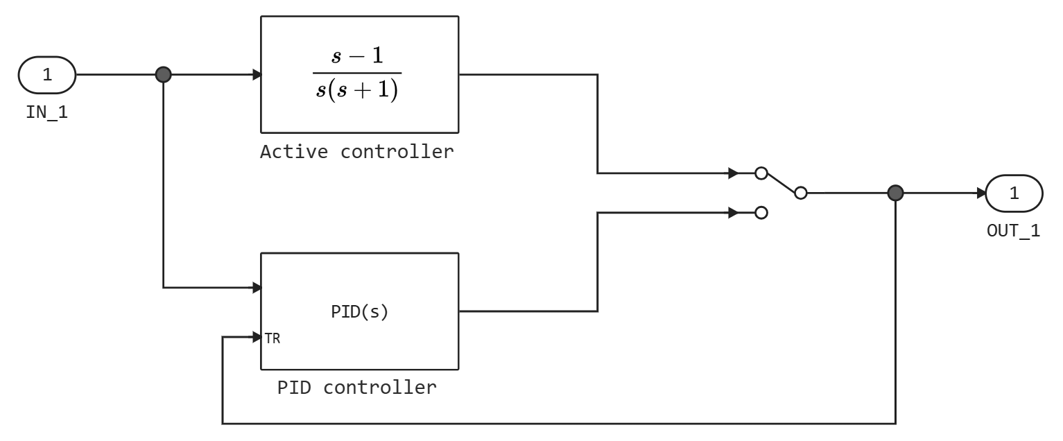
mainstructure management
Use signal tracking to prevent signal accumulation in control units in multi-circuit systems, as shown in the following model.
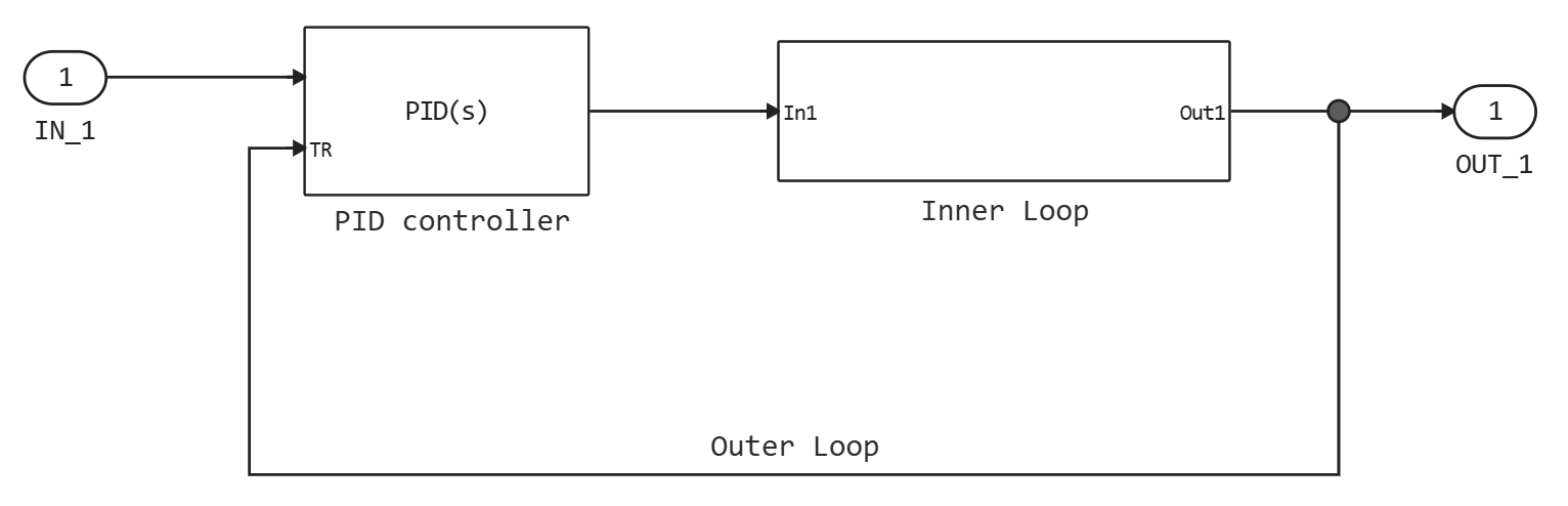
The subsystem of the Inner Loop contains the blocks shown in the following figure.
Since the PID controller monitors the output of the internal circuit, its output never exceeds the saturated output of the internal circuit.
Dependencies
To use this parameter, set for the parameter Controller: meaning PID, PI or I.
| Default value |
|
| Program usage name |
|
| Tunable |
No |
| Evaluatable |
Yes |
# Tracking coefficient (Kt): — signal tracking feedback loop gain
Details
When the checkbox is selected Enable tracking mode the difference between the TR signal and the output signal of the unit is fed back to the input of the gain integrator . Use this parameter to set the gain in this feedback loop.
For discrete controllers, if the check box is selected Use I*Ts (optimal for codegen), the value of this parameter will be equal to , where — the desired gain, and — the sampling period.
Dependencies
To use this option, check the box Enable tracking mode.
| Default value |
|
| Program usage name |
|
| Tunable |
No |
| Evaluatable |
Yes |
Saturation
Output saturation
# Limit output — limiting the output signal of the block to preset saturation values
Details
By checking this box, you can limit the output signal of the block, so a separate block Saturation after the regulator is not required. This also allows you to activate the built-in block protection mechanism against oversaturation (see the parameter description Anti-windup Method:).
Set the saturation limits of the output signal using the parameters Upper limit: and Lower limit:. You can also specify saturation limits externally via the input ports UpperLimit and LowerLimit by setting the parameter Source: meaning external in the parameter group Output saturation on the tab Saturation.
| Default value |
|
| Program usage name |
|
| Tunable |
No |
| Evaluatable |
Yes |
#
Source: —
source of output saturation limits
internal | external
Details
Use this parameter to set the upper and lower saturation limits of the output signal of the block.
-
internal— set the saturation limits of the output signal using the parameters Upper limit: and Lower limit:. -
external— set the saturation limits of the output signal externally using the input ports UpperLimit and LowerLimit.
Dependencies
To use this option, check the box Limit output in the parameter group Output saturation.
| Values |
|
| Default value |
|
| Program usage name |
|
| Tunable |
No |
| Evaluatable |
Yes |
# Upper limit: — upper saturation limit of the block output signal
Details
Specify the upper limit for the block output signal. The output signal of the unit is held at the upper saturation limit whenever the weighted sum of proportional, integral and differential actions exceeds this value.
Dependencies
To use this option, check the box Limit output in the parameter group Output saturation.
| Default value |
|
| Program usage name |
|
| Tunable |
No |
| Evaluatable |
Yes |
# Lower limit: — lower saturation limit of the block output signal
Details
Specify the lower limit for the output signal of the block. The output signal of the unit is kept at the lower saturation limit whenever the weighted sum of proportional, integral and differential actions falls below this value.
Dependencies
To use this option, check the box Limit output in the parameter group Output saturation.
| Default value |
|
| Program usage name |
|
| Tunable |
No |
| Evaluatable |
Yes |
Anti-windup
#
Anti-windup Method: —
the method of protection against oversaturation of the integrator
none | back-calculation | clamping | external
Details
When the checkbox is selected Limit output and if the weighted sum of the controller components exceeds the set limits of the output signal, the output signal of the unit remains at the set level. However, the output signal of the integrator may continue to grow (integrator oversaturation), increasing the difference between the output signal of the unit and the sum of the components of the unit. In other words, the internal signals in the unit can be unlimited, even if the output signal appears to be limited by saturation limits. Without a mechanism to prevent oversaturation of the integrator, two possible outcomes are:
-
If the sign of the input signal never changes, the integrator continues to integrate until overflow occurs. The overflow value is the maximum or minimum value for the data type of the integrator output.
-
If the sign of the input signal changes after the weighted sum has exceeded the limits of the output signal, it may take a long time to restore the operation of the integrator and return the weighted sum within the saturation limits of the block.
In any case, the regulator’s performance may decrease. To combat the effect of oversaturation without a mechanism to protect against oversaturation, it may be necessary to detune the regulator (for example, by reducing the gain coefficients), which will slow down its operation. To avoid this problem, activate the overload protection mechanism using this parameter.
-
none— the overload protection mechanism is not used. -
back-calculation— open the integrator when the output of the unit is saturated, feeding back to it the difference between the saturated and unsaturated control signal. The following figure shows a feedback circuit for a continuous regulator.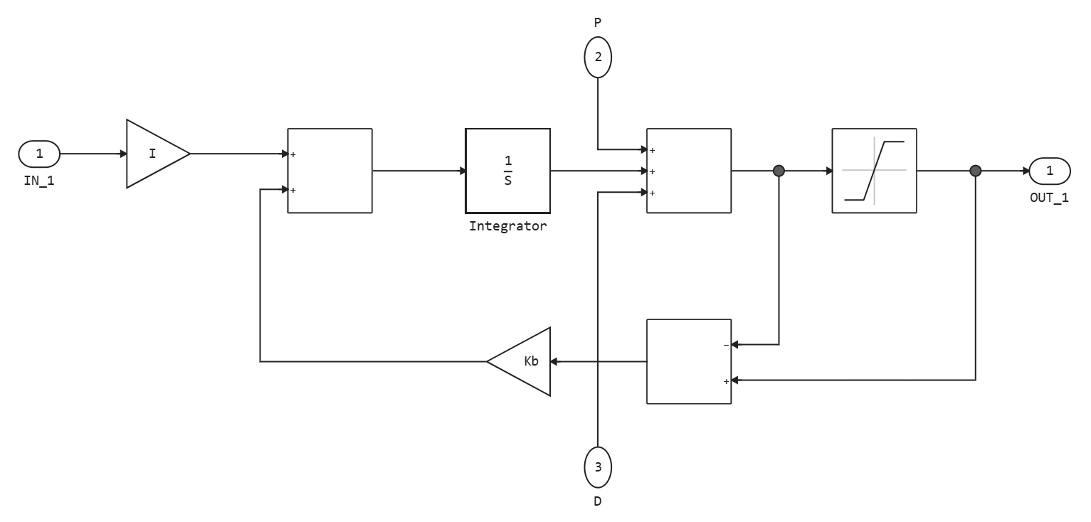
Use the parameter Back-calculation coefficient (Kb): to set the gain of the feedback loop that prevents saturation. Usually it is enough to install or for regulators with differential action . The reverse calculation can be effective for objects with a relatively long delay time [1].
-
clamping— sometimes the limitation of the signal is called conditional integration.Integration stops when both of the following conditions are met:
-
The sum of the block components exceeds the limits of the output signal.
-
The input signal of the integrator and the input signal of the saturation unit have the same sign.
Integration resumes when any of these conditions are no longer met. The limitation can be useful for objects with relatively short delay times, but it can lead to poor transient response with long delay times [1].
-
-
external— Built-in oversaturation protection methods are based on the fact that the sum of the block components exceeds the set limits of the block output signal. If there are saturations or limitations in the model after the PID controller blocks, you can use the extAW input port to implement custom overload protection logic. This block also provides a signal in front of the integrator on the preInt output port, which can be used as an input signal for a custom algorithm.
Dependencies
To use this option, check the box Limit output in the parameter group Output saturation.
| Values |
|
| Default value |
|
| Program usage name |
|
| Tunable |
No |
| Evaluatable |
Yes |
# Back-calculation coefficient (Kb): — feedback loop gain to prevent oversaturation
Details
Method back-calculation to prevent oversaturation, the integrator opens when the output of the block is saturated. This is done by feedback from the integrator of the difference between the saturated and unsaturated control signal. Use this parameter to set the gain factor. feedback loop to prevent oversaturation. For more information, see parameter description Anti-windup Method:.
For discrete controllers, if you check the box Use I*Ts (optimal for codegen), the value of this parameter will be equal to , where — the desired gain, and — the sampling period.
Dependencies
To use this option, check the box Limit output in the parameter group Output saturation and for the parameter Anti-windup Method: set the value back-calculation.
| Default value |
|
| Program usage name |
|
| Tunable |
No |
| Evaluatable |
Yes |
Integrator saturation
# Limit output — limiting the integrator’s output signal to preset saturation values
Details
By checking this box, you can limit the integrator’s output signal to a specified range. When the output signal of the integrator reaches the limits, the integrator will stop working to prevent oversaturation of the integral. Set the saturation limits using the parameters Upper limit: and Lower limit:.
| Default value |
|
| Program usage name |
|
| Tunable |
No |
| Evaluatable |
Yes |
# Upper limit: — upper limit of integrator saturation
Details
Specify the upper limit for the integrator output. The output signal of the integrator is held at this value whenever it would otherwise exceed this value.
Dependencies
To use this option, check the box Limit output in the parameter group Integrator saturation.
| Default value |
|
| Program usage name |
|
| Tunable |
No |
| Evaluatable |
Yes |
# Lower limit: — lower saturation limit of the integrator
Details
Specify the lower limit for the integrator output signal. The output signal of the integrator is held at this value whenever it would otherwise drop below this value.
Dependencies
To use this option, check the box Limit output in the parameter group Integrator saturation.
| Default value |
|
| Program usage name |
|
| Tunable |
No |
| Evaluatable |
Yes |
Examples
-
Simulation of a ventilation system in a building with a temperature control system
-
Simulation of the movement of an electric vehicle according to the WLTC cycle
-
The model of the automatic pressure control system (SARD) in the cockpit
-
Rapid prototyping of control algorithms at KPM RHYTHM: three-phase inverter