PV Array
|
Page in progress. |
Implementation of photovoltaic battery modules.
blockType: SubSystem
|
Path in the library: |
Description
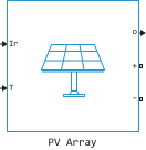
Block PV Array simulates an array of photovoltaic (PhotoVoltaic, PV) modules. The array consists of chains of modules connected in parallel, with each chain consisting of modules connected in series. The block allows you to model modules with custom parameters.
Block PV Array It is a model with five parameters, which uses a current source generated by the action of light. , diode, series resistance and parallel resistance to describe the volt-ampere characteristics of the modules, depending on the radiation intensity and temperature.
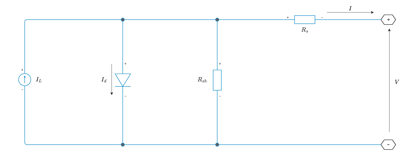
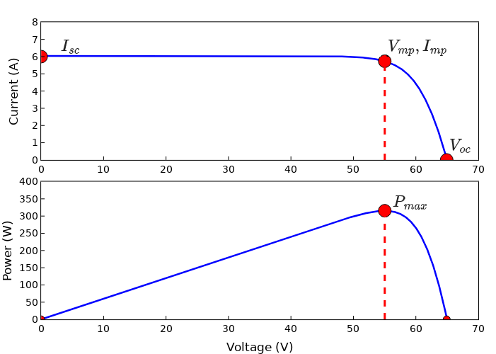
The volt-ampere characteristics of a diode for a single module are determined by the equations
where
-
— diode current, measured in amperes;
-
— saturation current of the diode, measured in amperes;
-
— diode voltage, measured in volts;
-
— Boltzmann constant, equal to
1.3806e−23J⋅K-1; -
— the temperature of the element, measured in kelvin;
-
— the charge of an electron equal to
1.6022e−19Cl; -
— the diode’s ideality coefficient, a number close to
1.0; -
— the number of elements connected in series in the module.
Ports
Input
#
Ir
—
a control signal that determines the intensity of radiation incident on solar panels, W/m^2 ^
scalar
Details
A control signal that determines the intensity of radiation incident on solar panels, set as a scalar in the range [0, 1000] W/m2.
| Data types |
|
| Complex numbers support |
I don’t |
#
T
—
control signal that determines the temperature of the elements, °C
scalar
Details
A control signal that determines the temperature of the elements, set as a scalar in degrees Celsius. The input value can be final negative, zero or positive.
| Data types |
|
| Complex numbers support |
I don’t |
Output
#
o
—
measurements
vector
Details
Measurement results returned as a vector of 5 elements. These signals can be selected using the block Bus Selector.
| The signal | Signal name | Definition |
|---|---|---|
|
|
The voltage of the photovoltaic battery, V |
|
|
The current of the photovoltaic battery, And |
|
|
Diode current, A |
|
|
Radiation intensity, W/m2 |
|
|
Temperature, °C |
| Data types |
|
| Complex numbers support |
I don’t |
Conserving
#
+
—
the positive pole
electricity
Details
A non-directional port connected to the positive pole of a photovoltaic battery.
| Program usage name |
|
#
−
—
the negative pole
electricity
Details
A non-directional port connected to the negative pole of a photovoltaic battery.
| Program usage name |
|
Parameters
Parameters
Array data
# Parallel strings — chains of modules connected in series, connected in parallel
Details
The number of chains of series-connected modules connected in parallel.
| Default value |
|
| Program usage name |
|
| Evaluatable |
Yes |
# Series-connected modules per string — photovoltaic modules connected in series in each circuit
Details
The number of photovoltaic modules connected in series in each chain.
| Default value |
|
| Program usage name |
|
| Evaluatable |
Yes |
Module data
# Cells per module Ncell — the number of elements in the module
Details
The number of elements in one module.
| Default value |
|
| Program usage name |
|
| Evaluatable |
Yes |
# Open circuit voltage Voc, V — open circuit voltage
Details
The voltage measured at the poles of a photovoltaic battery at a temperature of 25 °C, when the circuit is open.
| Default value |
|
| Program usage name |
|
| Evaluatable |
Yes |
# Short-circuit current Isc, A — short-circuit current
Details
The current that occurs when the poles of a photovoltaic battery are short-circuited at a temperature of 25 °C.
| Default value |
|
| Program usage name |
|
| Evaluatable |
Yes |
# Voltage at maximum power point Vmpp, V — voltage at the point of maximum power
Details
Voltage at the point of maximum power.
| Default value |
|
| Program usage name |
|
| Evaluatable |
Yes |
# Current at maximum power point Impp, A — current at the maximum power point
Details
Current at the maximum power point.
| Default value |
|
| Program usage name |
|
| Evaluatable |
Yes |
# Temperature coefficient of Voc, %/deg.C — dependence from the temperature
Details
Detects the change in the no-load voltage depending on the temperature. Meaning at a temperature of calculated using the formula
where
-
— no-load voltage at temperature ;
-
— no-load voltage at
25°C; -
— temperature coefficient, measured in %/°C;
-
— the temperature measured in degrees Celsius.
| Default value |
|
| Program usage name |
|
| Evaluatable |
Yes |
# Temperature coefficient of Isc, %/deg.C — dependence from the temperature
Details
Detects a change in the short-circuit current depending on the temperature. Meaning at a temperature of calculated using the formula
where
-
— short-circuit current at temperature ;
-
— short-circuit current at
25°C; -
— temperature coefficient, measured in %/°C);
-
— the temperature measured in degrees Celsius.
| Default value |
|
| Program usage name |
|
| Evaluatable |
Yes |
Module parameters
# Show module parameters — displaying the module model parameters
Details
Click this button to view the parameters of the photovoltaic module model in the window Model diagnostics:
-
Maximum power, W — power , obtained at the point of maximum power, calculated by the formula
where
-
— parameter value Voltage at maximum power point Vmpp, V;
-
— parameter value Current at maximum power point Impp, A.
-
-
Light-generated current IL, A — current for one module under standard test conditions, flowing from a controlled current source that simulates the current generated by light.
-
Diode saturation current I0, A — saturation current of the diode used to simulate a photovoltaic battery for one module under standard test conditions.
-
Diode ideality factor — the coefficient of ideality of a diode simulating a photovoltaic battery.
-
Shunt resistance Rsh, Ohm — parallel resistance of the model for one module under standard test conditions.
-
Series resistance Rs, Ohm — serial resistance of the model for one module under standard test conditions.
The values of all the parameters listed above, with the exception of Maximum power, W, are determined by the optimization function according to the characteristics of the module.
| Default value |
|
| Program usage name |
|
| Evaluatable |
No |
Advanced
Advanced
#
Break algebraic loop in internal model —
breaking the algebraic loop of the internal diode model
Continuous | Discrete
Details
Breaking the algebraic loop of the internal diode model.
-
In a continuous system (
Continuous) the algebraic loop is broken using a first-order filter. -
In a discrete system (
Discrete) the algebraic loop is broken using a time delay equal to one simulation step.If the sampling period is too long, this approach can lead to numerical fluctuations. For example, the block PV Array connected to the average model of the energy converter, can operate with a sampling period up to
50e−6seconds. In this case, the presence of an algebraic loop is necessary to obtain an accurate iterative solution taking into account the highly nonlinear characteristics of the diode. If the sampling period is small, for example1e−6seconds per block PV Array connected to a detailed model of a power electronic converter with real switches and a PWM inverter operating at a frequency of5kHz, breaking the algebraic loop allows you to speed up the simulation and ensure the accuracy of the solution.
The selected mode must match the parameter value. Synchronization type in the block Solver Configuration: if for Synchronization type the value is set Continuous, then it is necessary to select Continuous; if Discrete Then — Discrete.
| Values |
|
| Default value |
|
| Program usage name |
|
| Evaluatable |
Yes |
# Break loop time constant, s — the time constant of the filter breaking the algebraic loop
Details
The time constant of a first-order filter that breaks the algebraic loop of the internal diode model in continuous simulation.
Dependencies
To use this parameter, set for the parameter Break algebraic loop in internal model meaning Continuous.
| Default value |
|
| Program usage name |
|
| Evaluatable |
Yes |
# Break loop sample time, s — the sampling period at the break of the algebraic loop
Details
The sampling period when the algebraic loop of the internal diode model is broken using a time delay equal to one simulation step.
The value of this parameter must match the value of the parameter Sample time specified in the block Solver Configuration.
Dependencies
To use this parameter, set for the parameter Break algebraic loop in internal model meaning Discrete.
| Default value |
|
| Program usage name |
|
| Evaluatable |
Yes |