Artery Encoder
Reading the quadrature encoder through the microcontroller timer.
blockType: CFunction
|
Path in the library: |
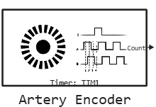
Description
| To work with the block, install/update the support package. equipment. |
Block Artery Encoder It is used to read a quadrature encoder connected to timer channels in encoder mode. In the first step, the timer starts in encoder mode. The timer counter value is output to the block output.
Configuring the AT32 Workbench
AT32 Workbench does not generate code for encoder mode automatically. A _ manual insertion of the call is required tmr_encoder_mode_config() in the user section of the generated file wk_tmr.c.
-
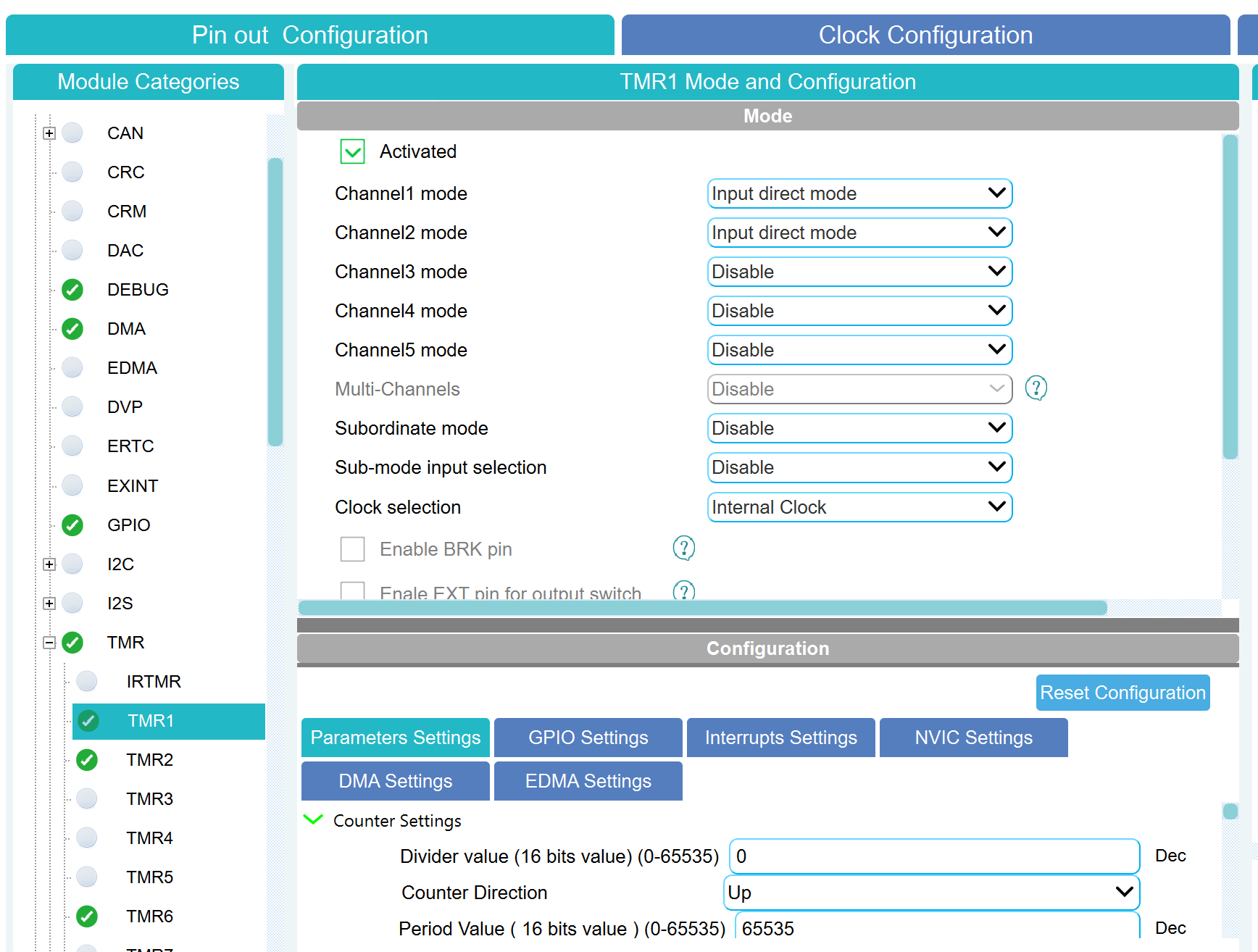
In AT32 Workbench, select the desired timer.
-
Set up two timer channels as inputs:
-
for Channel1 mode, set
Input direct mode; -
for Channel2 mode, set
Input direct mode; -
for other channels, set
Disable.
-
-
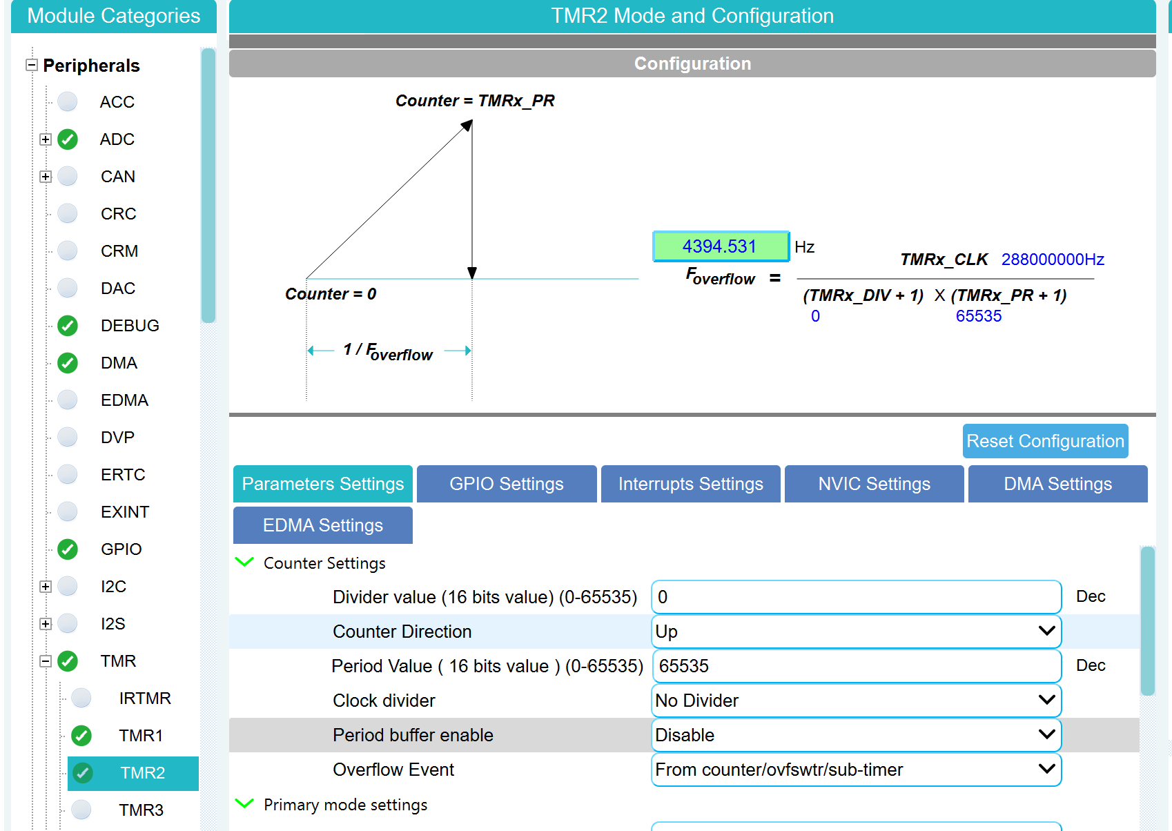
Configure the counter parameters in Counter Settings:
-
Period Value (ARR) — encoder resolution.
-
-
Generate the project (Generate Code).
-
Open the generated file
project/src/wk_tmr.c, find the functionwk_tmrX_init()(whereX— your timer number) and add a calltmr_encoder_mode_config()in the user section before GPIO initialization:/* add user code begin tmrX_init 1 */ tmr_encoder_mode_config(TMRX, TMR_ENCODER_MODE_C, TMR_INPUT_RISING_EDGE, TMR_INPUT_RISING_EDGE); /* add user code end tmrX_init 1 */Here
TMR_ENCODER_MODE_C— quadrature encoder mode (counting on both channels). Available modes:Mode Description TMR_ENCODER_MODE_AThe score on the fronts of TI1
TMR_ENCODER_MODE_BThe score on the fronts of TI2
TMR_ENCODER_MODE_CCounting on both channels (TI1+TI2) — for quadrature encoder
Ports
Output
#
Count
—
value of the encoder counter
scalar
Details
| Data types |
|
| Complex numbers support |
No |
Parameters
Main group
#
Таймер: —
microcontroller timer number
1 | 2 | 3 | 4 | 5 | 6 | 7 | 8 | 9 | 10 | 11 | 12 | 13 | 14 | 20
Details
| Values |
|
| Default value |
|
| Program usage name |
|
| Tunable |
No |
| Evaluatable |
Yes |