Artery PWM
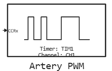
Generation of a PWM signal at the output of the microcontroller timer.
blockType: CFunction
|
Path in the library: |
Description
| To work with the block, install/update the support package. equipment. |
Block Artery PWM It is used to generate a PWM signal on a given timer channel. In the first step, the timer starts in PWM mode. The value at the input of the block determines the filling factor (borehole).
Configuring the AT32 Workbench
-
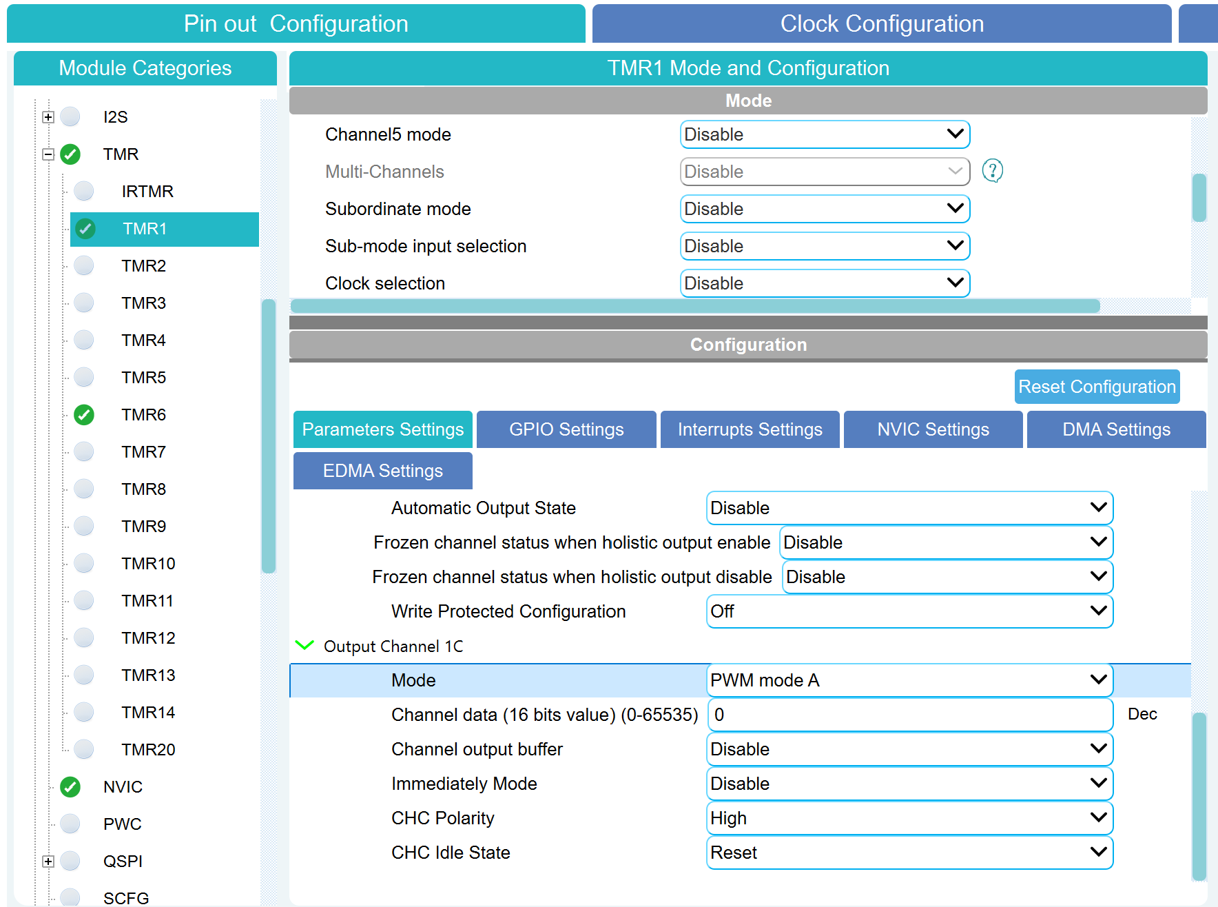
In AT32 Workbench, select the desired timer (TMR1–TMR14, TMR20).
-
Select the timer channel and set it to PWM mode A:
-
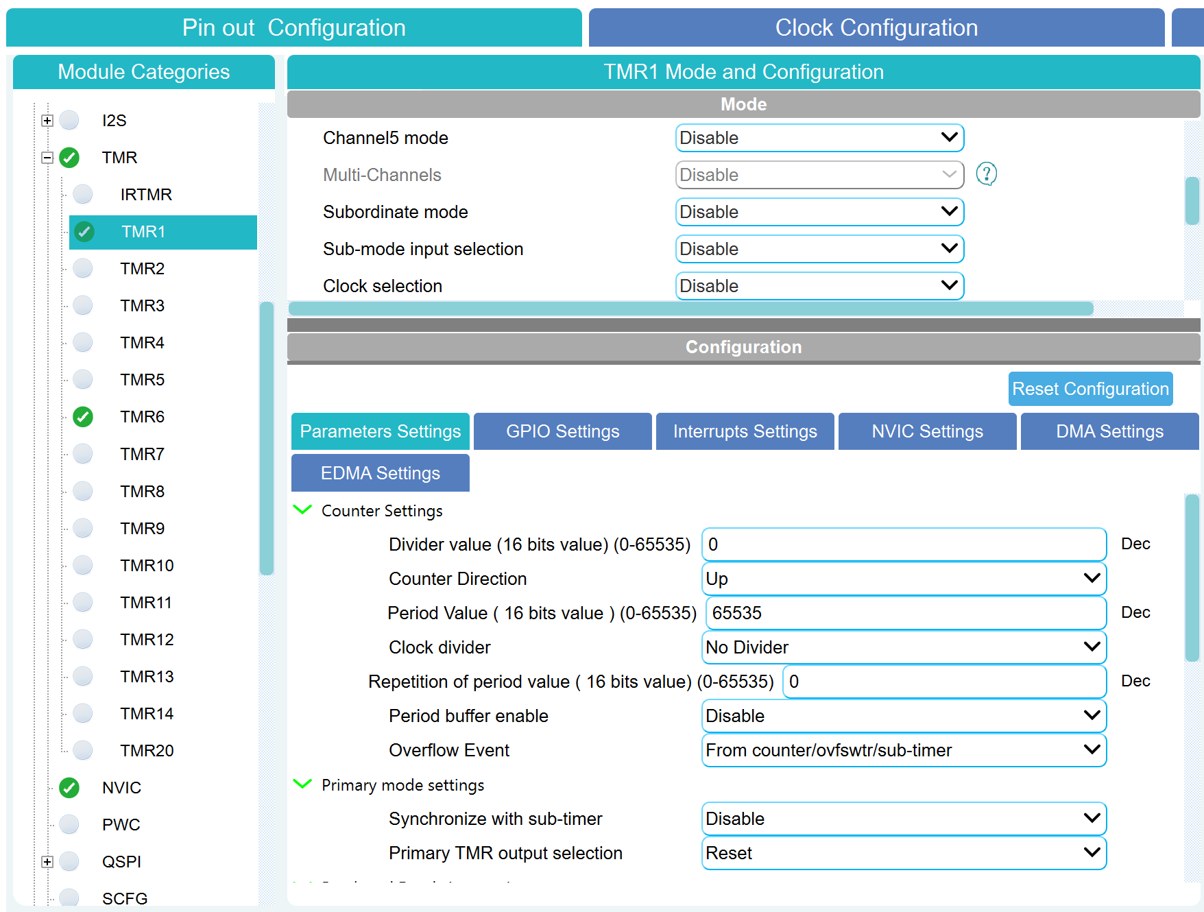
Configure the PWM parameters in Counter Settings:
-
Divider value (PSC) — divider;
-
Period Value (ARR) — PWM period (determines the resolution of the borehole).
-
-
Generate the project (Generate Code).
Ports
Input
#
CCRx
—
fill factor (duty cycle)
scalar
Details
| Data types |
|
| Complex numbers support |
No |
Parameters
Main group
#
Таймер: —
microcontroller timer number
1 | 2 | 3 | 4 | 5 | 6 | 7 | 8 | 9 | 10 | 11 | 12 | 13 | 14 | 20
Details
| Values |
|
| Default value |
|
| Program usage name |
|
| Tunable |
No |
| Evaluatable |
Yes |
#
Канал: —
timer channel number
1 | 2 | 3 | 4 | 5
Details
| Values |
|
| Default value |
|
| Program usage name |
|
| Tunable |
No |
| Evaluatable |
Yes |