Satellite cable stabilization system
This example demonstrates the creation of a system for stabilizing the angular position of the satellite by controlling the length of the cable with which it is attached to the platform. The control unit implemented with the help of finite automata controls the speed of cable winding and unwinding. The system allows you to reduce the amplitude of vibrations of a small satellite relative to the platform.
Description of the process being studied
Let's consider the problem of controlling the angular momentum of a satellite using a cable system. Cable stabilization ([Yo-yo despin](https://en.wikipedia.org/wiki/Yo-yo_de-spin It is often used to reduce the angular momentum of a satellite, intentionally created to stabilize during acceleration. But our system will control the satellite's oscillations around the space platform.
The system includes a small satellite connected to the platform by means of a long cable. When, due to various influences, the satellite connected to the platform begins to oscillate like a pendulum, the stabilization system is activated. To reduce the libration effect, the stabilization system will change the length of the cable, releasing it to its maximum length when the satellite is in the middle of the oscillation trajectory (which reduces its angular velocity) and retracts the cable back into those intervals when the angular velocity of the satellite is closer to zero.
The angular motion model
This model shows how the length of the cable is affects the angular velocity satellite movements.
The total energy of the satellite is calculated in the block Total Energy according to the formula:
In the block Compute theta_dot_dot the angular acceleration of the satellite is calculated during its movement at a distance from the platform:
The transition of the signal values through 0 is recorded using blocks HitCross, which form additional variables in the vector of the state of our system.
In the end, all 5 variables of this vector are transferred to the stabilization control unit, implemented as a finite state machine, using the component сhart.
The control unit
Below is a diagram of the control system implemented using the block chart.
.png)
When the satellite is in the middle of its periodic trajectory (at ), the system switches to the state ReelMovingOut. When the satellite has reached its maximum distance from the platform, the system switches to ReelStop. Then, when the angular velocity of the satellite passes the 0 mark, the system switches to the ReelMovingIn. And when the cable reaches the minimum allowable length, the system switches back to the ReelStop.
When the unit for calculating the total energy of the satellite returns a sufficiently small value, the stabilization system switches to Inactive.
Displaying results
Running the model allows you to see all the variables of the stabilization system state: the length of the cable l, satellite angle theta and their derivatives.
modelName = "satellite_yo_yo_model";
model = modelName in [m.name for m in engee.get_all_models()] ? engee.open( modelName ) : engee.load( "$(@__DIR__)/$(modelName).engee");

# Let's launch the model
s = engee.run( modelName, verbose=false )
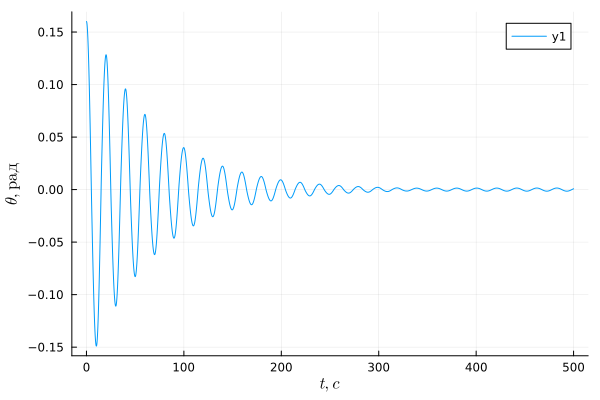
using Plots, LaTeXStrings
plot( s["theta"].time, s["theta"].value, xlabel=L"t, c", ylabel=L"\theta, I'm glad" )
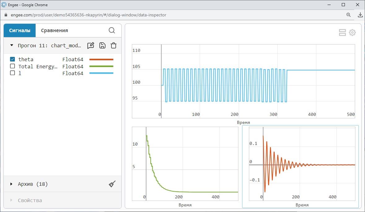
We use the data inspector to conveniently arrange all the graphs in one window.
.png)
As we can see, the energy of the system and the amplitude of the angular oscillations decreased as the stabilization system operated. On the blue graph, we can see how the length of the cable has changed – from the maximum allowable to the minimum.
Conclusion
By combining several types of models on one Engee canvas, we were able to visualize the process of controlling the tether stabilization system of a small satellite.