Simulation of traffic light control logic
The purpose of this example is to demonstrate the capabilities of the finite state machine library and to get acquainted with
its basic elements. We will consider the implementation of the simplest traffic light control logic using the Chart block.
The principle of operation
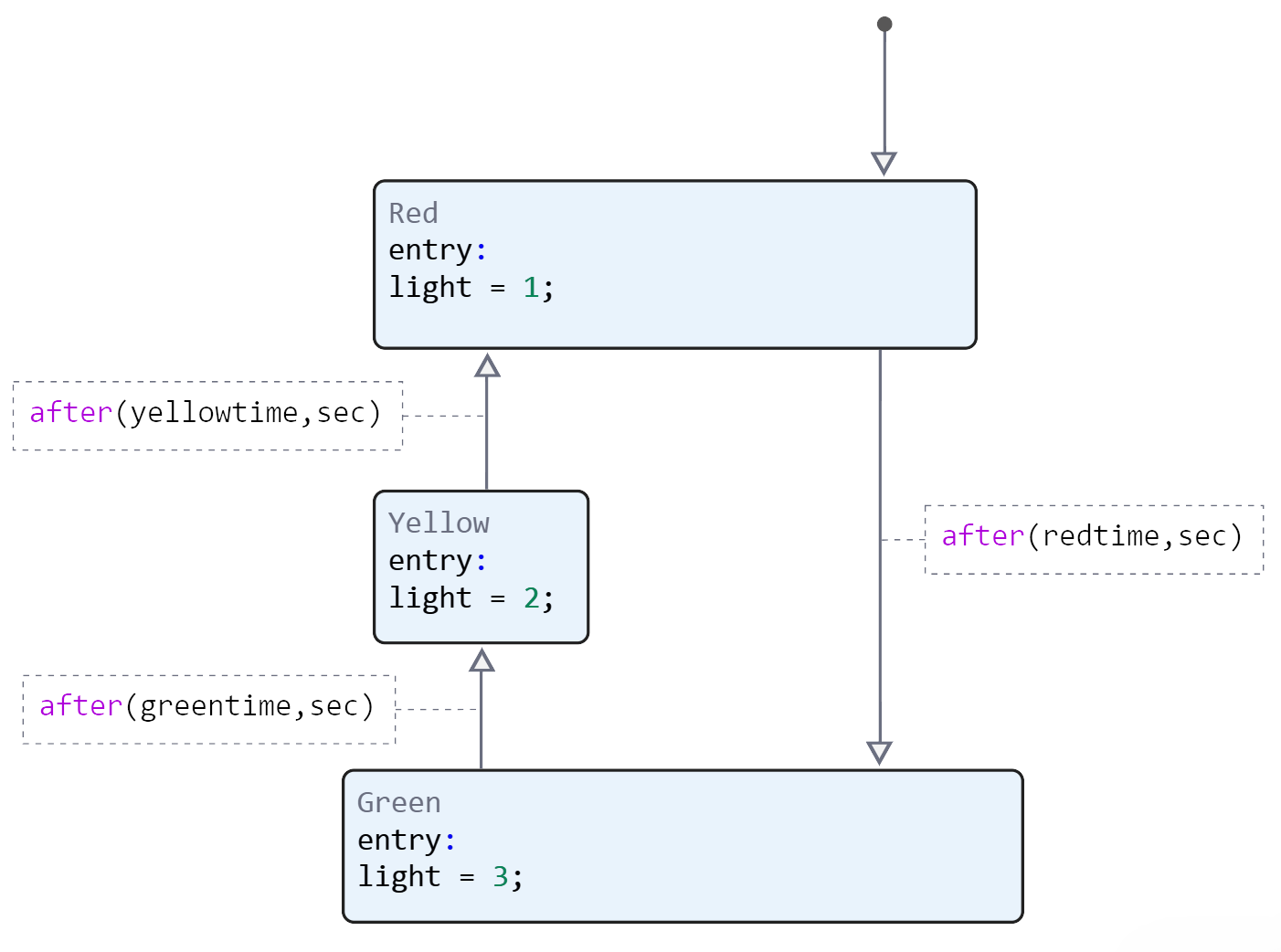
The traffic light has three colors and switches between them all the time. The moment when one of the colors is lit is called the state of the system. Accordingly, our model will have three states: Red, Yellow and Green. Red will be the default state, meaning each cycle will start from it.
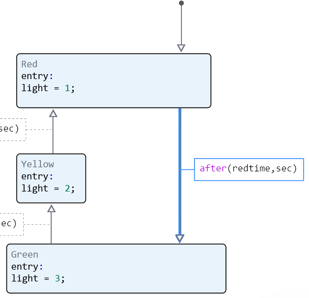
In this example, all transitions of the system from one state to another will be caused by the expiration of a set time. The Green state becomes active after the time specified in the function has passed. after().
We will set the time intervals as local variables: redtime, yellowtime, and greentime. We will also set the light output variable to output the results.
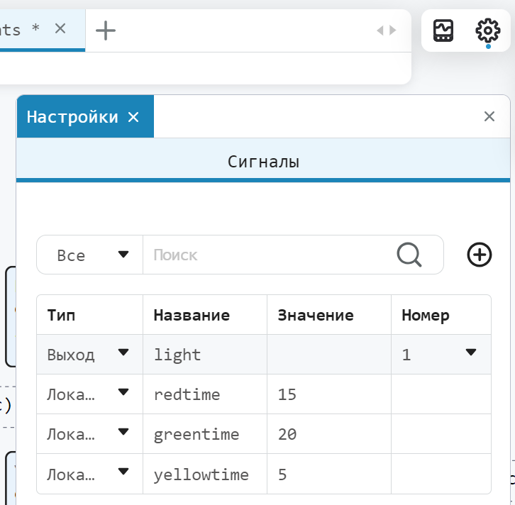
To monitor the operation of the system in each state, we will assign a certain value to the light output variable. For example, in a state where the red traffic light is on, we will assign the light value 1. In the state when yellow and green are lit, the values are 2 and 3, respectively.
Each of the states contains the entry operator, which indicates that the specified action is performed once when the state becomes active.
Conclusion of results
Let's run the model and look at the result.
# Enabling the auxiliary model launch function.
function run_model( name_model, path_to_folder )

    Path = path_to_folder * "/" * name_model * ".engee"

    if name_model in [m.name for m in engee.get_all_models()] # Checking the condition for loading a model into the kernel
        model = engee.open( name_model ) # Open the model
        model_output = engee.run( model, verbose=true ); # Launch the model
    else
        model = engee.load( Path, force=true ) # Upload a model
        model_output = engee.run( model, verbose=true ); # Launch the model
        engee.close( name_model, force=true ); # Close the model
    end

    return model_output
end
run_model("traffic_lights",@__DIR__) # Launching the model.
# Reading of encoded signals from simout
light = simout["traffic_lights/light"];
light = collect(light);
plot(light.time, light.value, label = "light")
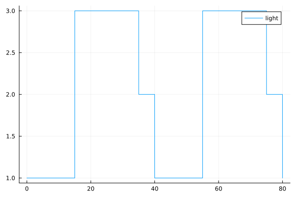
In the resulting graph, we can see how the traffic light signal changed. The red light was on for the first 15 seconds, then the green light was on for 20 seconds and the yellow light for 5 seconds,
then the cycle started again.
Conclusion
We have considered a simple implementation of the traffic light control logic using the Chart block of the finite state machine library. To learn more about the library, follow the link: https://engee.com/helpcenter/stable/articles/statemachines-first.html