Simulation of control logic with parallel states
To implement a parallel mode of operation, use parallel states in the library of finite automata. For example, as part of the design of a complex system, you can use parallel states to model independent components or subsystems that are active simultaneously.
Decomposition of the state
The type of decomposition of a diagram or state determines whether the diagram or state contains exclusive or parallel states.:
- Exclusionary states represent mutually exclusive modes of operation. No two exceptional states on the same hierarchical level can be active or executed simultaneously. In the transition diagrams, each exceptional state is represented by a solid rectangle.
- Parallel states represent independent modes of operation. Two or more parallel states can be active simultaneously, although they are executed sequentially. In the state diagrams, each parallel state is represented by a dotted rectangle with a number indicating the execution order.
You can combine exclusive and parallel states by defining the decomposition of states at different levels of your hierarchy of states. The default state decomposition type is Exclusive (OR). To change the decomposition type to Parallel (AND), right-click the parent state and select Decomposition > Parallel (AND). To change the decomposition type back to Exclusive (OR), right-click the parent state and select Decomposition > Exclusive (OR).
Air temperature controller
This example uses parallel decomposition modeling to simulate a regulator that maintains the air temperature at 120 degrees on a real object.
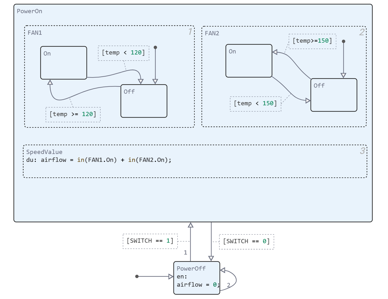
At the top level, the air controller circuit has two mutually exclusive states, PowerOff and PowerOn. The scheme uses a mutually exclusive activation (OR) strategy, because the controller cannot be turned on and off at the same time.
The controller controls two fans. The first fan turns on when the air temperature rises above 120 degrees. The second fan provides additional cooling when the air temperature rises above 150 degrees. In the diagram, these fans are represented as parallel substates FAN1 and FAN2 of the upper-level PowerOn state. Because fans work as independent components that turn on or off depending on the required cooling level. PowerOn uses a parallel activation circuit(S) so that both substates are active when the controller is turned on.
With the exception of threshold values, fans are modeled by states with identical configurations of substates and transitions that reflect two fan operating modes: On and Off. Since none of the fans can be turned on and off at the same time, FAN1 and FAN2 have a mutually exclusive circuit (OR).
In PowerOn, the third parallel state called SpeedValue is an independent subsystem that counts the number of fans turned on at each time step. The boolean expression in(FAN1.On) has the value 1 when On is the active state of FAN1. Otherwise, in(FAN1.On) is 0. Similarly, the value in(FAN2.On) indicates whether FAN2 is on or off. The sum of these expressions indicates the number of fans turned on at each time step.
Execution order for parallel states
Although FAN1, FAN2, and SpeedValue are active simultaneously, these states are executed sequentially during simulation. The numbers in the upper right corners of the states determine the order of execution. The rationale for this execution procedure is as follows:
- FAN1 Runs first because it turns on at a lower temperature than FAN2. It can turn on regardless of whether FAN2 is on or off.
- FAN2 runs second because it turns on at a higher temperature than FAN1. It can only turn on if FAN1 is already on.
- The SpeedValue is executed last so that the most current state of FAN1 and FAN2 can be monitored.
By default, the order in which parallel states are executed is determined according to the order in which you add them to the diagram. To change the execution order of a parallel state, right-click on it and select a value from the drop-down list. The order of execution.
Study the model
This model contains a state diagram Air temperature controller
and a subsystem called Physical Object.

Depending on the air temperature on the physical installation, the diagram turns on the fans and outputs the number of working airflow fans to the subsystem. This value determines the cooling efficiency coefficient. according to these rules:
-
airflow = 0 — the fans are not working. The air temperature does not decrease because .
-
airflow = 1 — one fan is running. The air temperature decreases in accordance with the cooling efficiency coefficient .
-
airflow = 2 — two fans are running. The air temperature decreases in accordance with the cooling efficiency coefficient .
The subsystem "Physical object" updates the air temperature inside the object based on the equations
where:
-
is the initial temperature. The default value is 70°.
-
is the ambient temperature. The default value is 160°.
-
— the heat transfer coefficient for the installation. The default value is 0.01.
-
- coefficient of cooling activity corresponding to airflow.
The new temperature determines the degree of cooling in the next time step of the simulation.
Let's see how the air temperature controller works. Let's run the model using command control.
modelName = "parallel_st_fan";
PID_model = modelName in [m.name for m in engee.get_all_models()] ? engee.open( modelName ) : engee.load( "$(@__DIR__)/$(modelName).engee");
results = engee.run( modelName )
plot(
    plot(results["Tout"].time, results["Tout"].value, lab = "Tout"),
    plot(results["Switch"].time, results["Switch"].value, lab = "Switch", c="red"),
    layout = (2,1)
)
Conclusion
We have considered the modeling of control logic using parallel states of finite automata. This tool allows you to implement variants of models in which several independent states of the system need to work.