Earthing Transformer
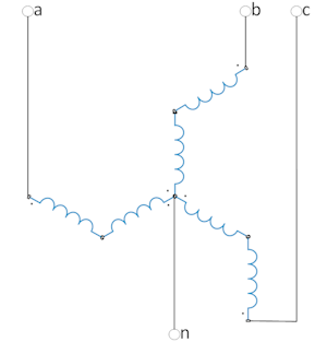
A three-phase neutral grounding transformer with a winding connection according to the Zigzag scheme.
blockType: AcausalElectricPowerSystems.Passive.Transformers.Earthing
|
Path in the library: |

Description
Block Earthing Transformer It is a three-phase neutral grounding transformer with a winding connection according to the Zigzag scheme. This unit allows you to create an artificial neutral in an ungrounded three-phase power supply system. The artificial neutral creates a low-resistance path for the zero-sequence current and a high-resistance path for the direct sequence current. The presence of a common point allows the use of a voltage source connected according to the Triangle scheme to connect a single-phase load.
For more information about the operating modes of a three-phase system connected according to the Triangle scheme, see Recommendations for delta connection of transformer windings.
The equations
This unit is implemented in both the electrical and magnetic fields, representing the physics of phase windings and a magnetic core. An equivalent block diagram includes blocks Reluctance, Winding and Eddy Current (Physical Modeling Electrical Passive).
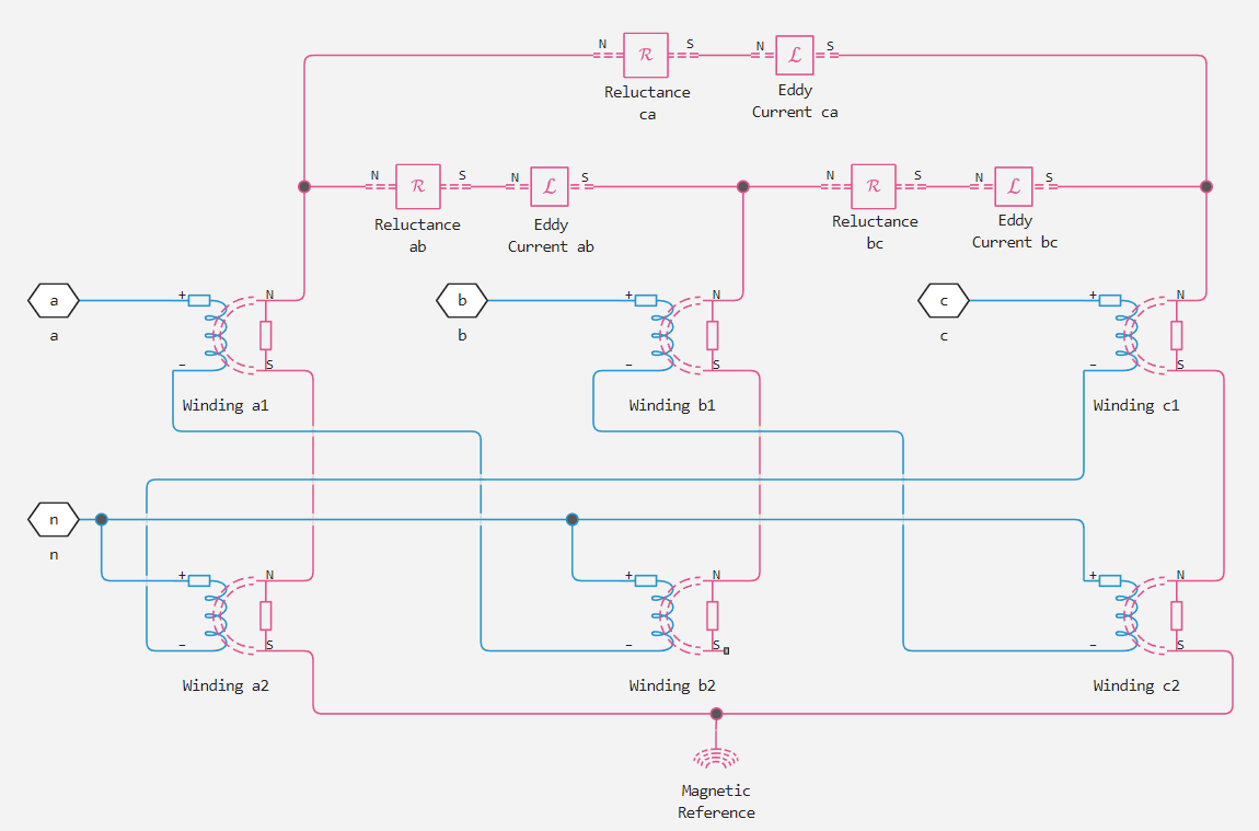
When the windings are zigzagged, phases a, b, and c represent each rod of the magnetic core.
The relationship between electrical and magnetic properties can be obtained by applying several mathematical steps based on the rule of conservation of magnetic flux and Ohm’s law for a magnetic circuit.
For grounding transformers, the connections between the phases and all windings are the same.
In the equations below:
-
— the number of turns of the winding;
-
— magnetizing resistance between phases;
-
— leakage resistance of the primary winding;
-
— the conductivity of the eddy current loop between the phases.
Then the relationship between the inductance matrix in the electrical domain and the inductance matrix in the magnetic domain can be written as:
The diagonal elements are the sum of the scattering inductance and the magnetizing inductance for each phase, so that:
Therefore:
Variables
Use the parameter group Initial Targets to set the priority and initial target values for the block parameter variables before modeling. For more information, see Configuring physical blocks using target values.
Parameters
Main
#
Rated apparent power —
Rated full power
W | uW | mW | kW | MW | GW | V*A | HP_DIN
Details
The rated power passing through the transformer. The value must be greater than 0.
| Units |
|
| Default value |
|
| Program usage name |
|
| Evaluatable |
Yes |
#
Rated voltage —
RMS line voltage
V | uV | mV | kV | MV
Details
The nominal RMS line voltage.
The value must be higher 0.
| Units |
|
| Default value |
|
| Program usage name |
|
| Evaluatable |
Yes |
#
Rated electrical frequency —
Rated electrical frequency
Hz | kHz | MHz | GHz
Details
The nominal or nominal frequency of the AC network to which the transformer is connected. The value should be higher 0.
| Units |
|
| Default value |
|
| Program usage name |
|
| Evaluatable |
Yes |
Impedances
#
Units —
the system of units of measurement
Per unit | SI
Details
A system of units for parameterization of impedance.
Dependencies
The use of other parameters depends on the value of this parameter.
| Values |
|
| Default value |
|
| Program usage name |
|
| Evaluatable |
No |
# Zero-sequence resistance, pu — zero sequence resistance
Details
Zero sequence resistance in relative units.
The value must be higher 0.
Dependencies
To use this parameter, set for the parameter Units meaning Per unit.
| Default value |
|
| Program usage name |
|
| Evaluatable |
Yes |
# Zero-sequence reactance, pu — zero sequence reactivity
Details
The reactance of the zero sequence in relative units. The value must be greater than or equal to the magnetic flux losses of the primary winding.
Dependencies
To use this parameter, set for the parameter Units meaning Per unit.
| Default value |
|
| Program usage name |
|
| Evaluatable |
Yes |
# Shunt magnetizing resistance, pu — core magnetization resistance
Details
The magnetization resistance of the core in relative units. The value must be higher 0.
Dependencies
To use this parameter, set for the parameter Units meaning Per unit.
| Default value |
|
| Program usage name |
|
| Evaluatable |
Yes |
# Shunt magnetizing reactance, pu — magnetic inductance of the transformer core
Details
The magnetic inductance of the transformer core when operating in its linear region in relative units. The value must be higher 0.
Dependencies
To use this parameter, set for the parameter Units meaning Per unit.
| Default value |
|
| Program usage name |
|
| Evaluatable |
Yes |
#
Zero-sequence resistance —
zero sequence resistance
Ohm | mOhm | kOhm | MOhm | GOhm
Details
Zero sequence resistance. The value must be higher 0.
Dependencies
To use this parameter, set for the parameter Units meaning SI.
| Units |
|
| Default value |
|
| Program usage name |
|
| Evaluatable |
Yes |
#
Zero-sequence inductance —
zero-sequence inductance
H | nH | uH | mH
Details
The inductance of the zero sequence. The value must be higher 0.
Dependencies
To use this parameter, set for the parameter Units meaning SI.
| Units |
|
| Default value |
|
| Program usage name |
|
| Evaluatable |
Yes |
#
Shunt magnetizing resistance —
core magnetization resistance
Ohm | mOhm | kOhm | MOhm | GOhm
Details
The magnetization resistance of the core. The value must be higher 0.
Dependencies
To use this parameter, set for the parameter Units meaning SI.
| Units |
|
| Default value |
|
| Program usage name |
|
| Evaluatable |
Yes |
#
Shunt magnetizing inductance —
magnetic inductance of the transformer core
H | nH | uH | mH
Details
The magnetic inductance of the transformer core when operating in its linear region. The value must be higher 0.
Dependencies
To use this parameter, set for the parameter Units meaning SI.
| Units |
|
| Default value |
|
| Program usage name |
|
| Evaluatable |
Yes |