Tap-Changing Transformer
A single-phase transformer with switching windings.
blockType: AcausalElectricPowerSystems.Passive.Transformers.TapChanging
|
Path in the library: |

Description
Block Tap-Changing Transformer It is a single-phase transformer with switching windings. You can change the ratio of the transformer turns during the simulation using the control input.
Use this unit to adjust or change the output voltage of a linear transformer during simulation. To simulate the saturation effect, use the block Nonlinear Transformer.
The principle of operation
The signal on the input port c is used to change the position of the transformer winding switch.
If the signal on port c exceeds the positive value of the parameter Control threshold, t, the position of the winding switch p increases by one.
If the signal on port c is lower than the negative value of the parameter Control threshold, t, the position of the winding switch p decreases by one.
This figure shows the reaction of the winding switch to the control signal.
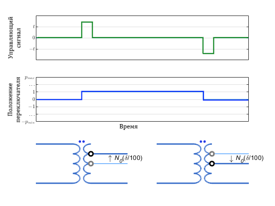
On the diagram:
-
— the nominal number of winding turns of the winding switch;
-
— percentage change in the number of turns per step step. Set this value using the Change per tap (%) parameter;
-
and — minimum and maximum allowable switching indexes. Set these values using the parameters Minimum tap index (nominal=0) and Maximum tap index (nominal=0).
To select the winding of the winding switch, use the parameter Tap-changer location. The overall transformation coefficient depends on this parameter. :
-
Primary winding
.
-
Secondary winding
.
Where — nominal transformation coefficient.
The equivalent scheme
The equivalent scheme is shown in the figure.
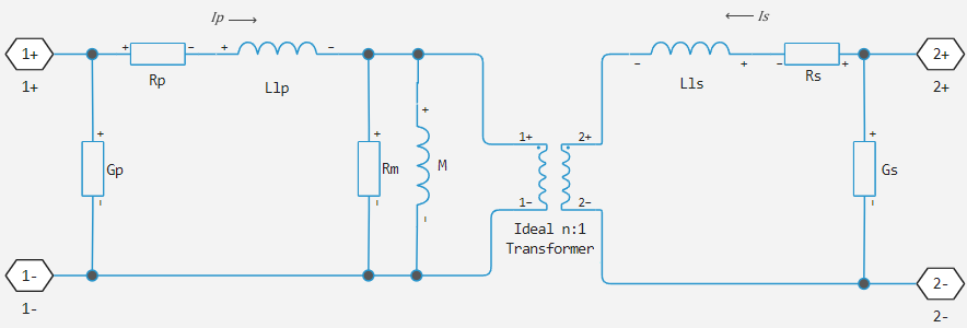
Here:
-
and — sequential resistances of the primary and secondary windings, respectively. Changing the position of the winding switch affects these values.;
-
and — the scattering inductance of the primary and secondary windings, respectively. Changing the position of the winding switch affects these values.;
-
and — magnetization resistance and inductance, respectively. Changing the position of the winding switch affects these values.;
-
— the transformation coefficient;
-
and ` — the scattering conductivity of the primary and secondary windings, respectively. Changing the position of the winding switch does not affect these values.
Variables
Use the parameter group Initial Targets to set the priority and initial target values for the block parameter variables before modeling. For more information, see Configuring physical blocks using target values.
Ports
Conserving
#
1+
—
positive terminal 1 of the line
electricity
Details
The electrical port represents terminal 1 of the line with positive polarity.
| Program usage name |
|
#
1−
—
negative terminal 1 of the line
electricity
Details
The electrical port represents terminal 1 of the line with negative polarity.
| Program usage name |
|
#
2+
—
Positive terminal 2 lines
electricity
Details
The electrical port represents terminal 2 of the line with positive polarity.
| Program usage name |
|
#
2−
—
Negative terminal 2 lines
electricity
Details
The electrical port represents terminal 2 of the line with negative polarity.
| Program usage name |
|
Input
#
c
—
control signal
scalar
Details
The input signal controlling the position of the winding switch.
| Data types |
|
| Complex numbers support |
No |
Parameters
Main
# Turns ratio (primary/secondary) — transformation coefficient
Details
The transformation coefficient is at the nominal position of the winding switch. The transformation coefficient is defined as the number of turns of the primary winding divided by the number of turns of the secondary winding.
| Default value |
|
| Program usage name |
|
| Evaluatable |
Yes |
#
Primary leakage inductance —
scattering inductance on the primary winding
H | nH | uH | mH
Details
The inductance, which represents the magnetic flux loss of the primary winding.
| Units |
|
| Default value |
|
| Program usage name |
|
| Evaluatable |
Yes |
#
Secondary leakage inductance —
the scattering inductance on the secondary winding
H | nH | uH | mH
Details
The inductance, which represents the losses on the magnetic flux of the secondary winding.
| Units |
|
| Default value |
|
| Program usage name |
|
| Evaluatable |
Yes |
#
Core-loss resistance —
magnetization resistance
Ohm | mOhm | kOhm | MOhm | GOhm
Details
The magnetization resistance for the transformer.
| Units |
|
| Default value |
|
| Program usage name |
|
| Evaluatable |
Yes |
#
Magnetization inductance —
magnetization inductance
H | nH | uH | mH
Details
The magnetization inductance for the transformer.
| Units |
|
| Default value |
|
| Program usage name |
|
| Evaluatable |
Yes |
#
Primary series resistance —
resistance of the primary winding
Ohm | mOhm | kOhm | MOhm | GOhm
Details
The series resistance of the primary winding.
| Units |
|
| Default value |
|
| Program usage name |
|
| Evaluatable |
Yes |
#
Secondary series resistance —
resistance of the secondary winding
Ohm | mOhm | kOhm | MOhm | GOhm
Details
The series resistance of the secondary winding.
| Units |
|
| Default value |
|
| Program usage name |
|
| Evaluatable |
Yes |
#
Primary leakage conductance —
scattering conductivity of the primary winding
S | nS | uS | mS | 1/Ohm
Details
The scattering conductivity of the primary winding. Set this value to non-zero to achieve numerical convergence in some circuit topologies.
| Units |
|
| Default value |
|
| Program usage name |
|
| Evaluatable |
Yes |
#
Secondary leakage conductance —
scattering conductivity of the secondary winding
S | nS | uS | mS | 1/Ohm
Details
The scattering conductivity of the secondary winding. Set this value to non-zero to achieve numerical convergence in some circuit topologies.
| Units |
|
| Default value |
|
| Program usage name |
|
| Evaluatable |
Yes |
Tap
#
Tap-changer location —
winding of the winding switch
Primary | Secondary
Details
Specify on which winding the switch of the windings is located: primary or secondary.
| Values |
|
| Default value |
|
| Program usage name |
|
| Evaluatable |
No |
# Minimum tap index (nominal=0) — minimum position of the winding switch
Details
The minimum allowable position of the winding switch.
| Default value |
|
| Program usage name |
|
| Evaluatable |
Yes |
# Maximum tap index (nominal=0) — maximum position of the winding switch
Details
The maximum allowable position of the winding switch.
| Default value |
|
| Program usage name |
|
| Evaluatable |
Yes |
# Change per tap, % — position change step
Details
The percentage change in the number of turns of the winding switch per position step. Set this value so that the absolute percentage change at the minimum and maximum position indices is less 100%.
| Default value |
|
| Program usage name |
|
| Evaluatable |
Yes |
# Control threshold — shift threshold
Details
The control value at which the position of the winding switch changes. To reduce the position of the winding switch, apply a control signal less than this value. To increase the position of the winding switch, apply a control signal greater than this value.
| Default value |
|
| Program usage name |
|
| Evaluatable |
Yes |