Nonlinear Transformer
Transformer with a non-ideal core.
blockType: AcausalElectricPowerSystems.Passive.Transformers.Nonlinear
|
Nonlinear Transformer Path in the library: |
|
Three-Winding Nonlinear Transformer Path in the library: |
|
Multi-Winding Nonlinear Transformer Path in the library: |


Description
The unit Nonlinear Transformer is a transformer with a non-ideal core. The core can be non-ideal due to its magnetic properties and dimensions.
The equivalent circuit of a two-winding transformer depends on which of the two options is used for the parameters Winding parameterized by:
-
Combined primary and secondary values.
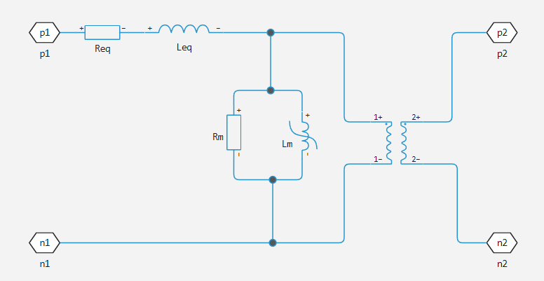
-
Separate primary and secondary values.
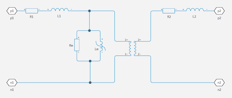
where
-
Reqis the total active resistance of the winding; -
Leq- total scattering inductance; -
R1- active resistance of the primary winding; -
L1- scattering inductance of the primary winding; -
R2- active resistance of the secondary winding; -
L2- scattering inductance of the secondary winding; -
Rm- active magnetising resistance; -
Lm- magnetising inductance.
The figure below shows the equivalent circuit of a three-winding transformer:
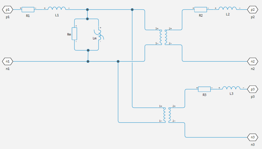
where
-
R1- active resistance of the primary winding; -
L1- scattering inductance of the primary winding; -
R2- active resistance of the first secondary winding; -
L2- scattering inductance of the first secondary winding; -
R2- active resistance of the second secondary winding; -
L2- scattering inductance of the second secondary winding; -
Rm- active magnetising resistance; -
Lm- magnetising inductance.
The block provides the following options for parameterization of nonlinear magnetising inductance:
Single inductance (linear)
The relationships between voltage, current and magnetic flux are defined by the following equations:
,
,
,
where
-
- terminal voltage;
-
- current through the terminals;
-
- current through the transformer magnetising inductance;
-
- parasitic parallel conductivity;
-
- number of turns of the first winding;
-
- magnetic flux;
-
- unsaturated inductance.
One saturation point
The relationships between voltage, current and magnetic flux are defined by the following equations:
,
,
(up to the saturation point),
(after the saturation point),
where
-
- terminal voltage;
-
- current through the terminals;
-
- current through the transformer magnetising inductance;
-
- parasitic parallel conductivity;
-
- number of turns of the first winding;
-
- magnetic flux;
-
- magnetic flux saturation bias;
-
- unsaturated inductance;
-
- saturated inductance.
Characterisation of the dependence of magnetic flux on current
The relationships between voltage, current and flux are defined by the following equations:
,
,
,
where
-
- terminal voltage;
-
- current through the terminals;
-
- current through the transformer magnetising inductance;
-
- parasitic parallel conductivity;
-
- number of turns of the first winding;
-
- magnetic flux.
The magnetic flux is determined using a one-dimensional table consisting of a vector of current values and a vector of corresponding magnetic flux values. Both negative and positive values can be used to specify these vectors, or only positive values can be used. If only positive data are used, the vector must start at 0, while negative data will be automatically calculated by symmetrical mapping with respect to the point (0,0).
Characterisation of the dependence of magnetic induction on magnetic field strength
The relationships between voltage, current and flux are defined by the following equations:
,
,
,
,
,
where
-
- terminal voltage;
-
- current through the terminals;
-
- current through the transformer magnetising inductance;
-
- parasitic parallel conductivity;
-
- number of turns of the first winding;
-
- magnetic flux;
-
- magnetic induction;
-
- magnetic field strength;
-
- effective core length;
-
- effective cross-sectional area of the core.
Magnetic induction is determined using a one-dimensional table consisting of a vector of magnetic field strength values and a vector of corresponding magnetic induction values. Both negative and positive values can be used to specify these vectors, or only positive values can be used. If only positive data are used, the vector must start at 0, while negative data will be automatically calculated by symmetric mapping with respect to the point (0,0).
Characterisation of the dependence of magnetic induction on magnetic field strength with hysteresis
The relationships between voltage, current and flux are defined by the following equations:
,
,
,
,
,
where
-
- terminal voltage;
-
- current through the terminals;
-
- current through the transformer magnetising inductance;
-
- parasitic parallel conductivity;
-
- number of turns of the first winding;
-
- magnetic flux;
-
- magnetic induction;
-
- magnetic constant;
-
- magnetic field strength;
-
- core magnetisation;
-
- effective core length;
-
- effective cross-sectional area of the core.
Magnetisation leads to an increase in magnetic induction, and its magnitude depends on both the current value of the field strength , and its previous variation over time. The equations of the Giles-Atherton model are used to determine at any point in time.
The starting point for the Giles-Atherton equation is to separate the magnetisation effect into two parts, one of which is purely a function of the effective field strength ( ) and the other is an irreversible part that depends on past history:
.
The member is called the anhysteresis magnetisation because it has no hysteresis. It is described by the following function on the current value of the effective field strength :
.
This function defines a saturation curve with limit values and a saturation point determined by the value of , the shape factor of the anhysteresis curve. It can be roughly considered to describe the average of the two hysteresis curves. In the block Nonlinear Transformer we set the values at and points on the angysteresis curve B-H, which are used to determine the values of and .
The parameters is the reversible magnetisation coefficient and determines which part of the behaviour is determined by , and which part is determined by the irreversible term . In the Giles-Atherton model, the irreversible term is determined by the partial derivative of the field strength:
.
Comparison of this equation with the standard first order differential equation shows that as the field strength H increases, the irreversible term follows the reversible term , but with a variable gain .
The tracking error serves to create hysteresis at points where changes sign. The main parameter that forms the irreversible characteristic is , which is called the bulk coupling coefficient. The parameter is called the interdomain coupling coefficient and is also used to determine the effective field strength used to construct the angysteresis curve:
The value of affects the shape of the hysteresis curve: the larger it is, the higher the curve intersects the B-axis. However, it should be noted that the term , which must be positive at and negative at , is necessary for stability. Therefore, not all values of α are acceptable; a typical maximum value is of the order of 1e-3.
Procedure for finding approximate values of the coefficients of the Giles-Atherton equation
The following procedure can be used to determine suitable parameters for the coefficients of the equation:
-
Specify the value of the parameters Anhysteretic B-H gradient when H is zero ( at ) plus the data point on the B-H anti-hysteresis curve. From these values, the values and are determined during block initialisation.
-
Set the value for the parameters Coefficient for reversible magnetization, c, so as to achieve the correct initial B-H derivative when the simulation is run from the point . The value of is approximately equal to the ratio of this initial derivative to Anhysteretic B-H gradient when H is zero. The value of must be greater than
0and less than1. -
Set the value for the Bulk coupling coefficient, K, A/m parameters to approximately equal the value of when is on a positive hysteresis curve.
-
Start with a very small value of and gradually increase it to adjust the value of when it crosses the line . A typical value is in the range of
1e-4to1e-3. Values that are too large cause the derivative of the B-H curve to tend to infinity, which is unphysical and results in a run-time assertion error.
It may be necessary to perform these steps several times to get a good match with the predefined B-H curve.
Volt-ampere characteristic (VAC)
Based on the specified VAC, the magnetic induction vectors and current vectors are calculated for usage of the magnetic flux-current characteristic:
,
,
where
-
- vectors defining the transformer VAC, parameters Voltage vector in RMS, v and Current vector in RMS, i respectively;
-
- number of turns of the first winding, the value of the parameters First winding number of turns;
-
- network frequency, value of the parameters System frequency.
Ports
Conserving
#
1+
—
positive terminal of the first winding
electricity
Details
Electrical port, represents the terminal of the first winding with positive polarity.
| Program usage name |
|
#
1-
—
negative terminal of the first winding
electricity
Details
Electrical port, represents the terminal of the first winding with negative polarity.
| Program usage name |
|
#
2+
—
positive terminal of the second winding
electricity
Details
Electricity port, represents the terminal of the second winding with positive polarity.
| Program usage name |
|
#
2-
—
negative terminal of the second winding
electricity
Details
Electricity port, represents the terminal of the second winding with negative polarity.
| Program usage name |
|
#
3+
—
positive terminal of the third winding
electricity
Details
Electricity port, represents the terminal of the third winding with positive polarity.
Dependencies
To use this port, set the parameters to Number of windings value Three, Four, Five or Six.
| Program usage name |
|
#
3-
—
negative terminal of the third winding
electricity
Details
Electricity port, represents the terminal of the third winding with negative polarity.
Dependencies
To use this port, set the parameters to Number of windings value Three, Four, Five or Six.
| Program usage name |
|
#
4+
—
positive terminal of the fourth winding
electricity
Details
Electricity port, represents the terminal of the fourth winding with positive polarity.
Dependencies
To use this port, set the parameters to Number of windings value Four, Five or Six.
| Program usage name |
|
#
4-
—
negative terminal of the fourth winding
electricity
Details
Electricity port, represents the terminal of the fourth winding with negative polarity.
Dependencies
To use this port, set the parameters to Number of windings value Four, Five or Six.
| Program usage name |
|
#
5+
—
positive terminal of the fifth winding
electricity
Details
Electricity port, represents the terminal of the fifth winding with positive polarity.
Dependencies
To use this port, set the parameters to Number of windings value Five or Six.
| Program usage name |
|
#
5-
—
negative terminal of the fifth winding
electricity
Details
Electricity port, represents the terminal of the fifth winding with negative polarity.
Dependencies
To use this port, set the parameters to Number of windings value Five or Six.
| Program usage name |
|
#
6+
—
positive terminal of the sixth winding
electricity
Details
Electricity port, represents the terminal of the sixth winding with positive polarity.
Dependencies
To use this port, set the parameters to Number of windings value Six.
| Program usage name |
|
#
6-
—
negative terminal of the sixth winding
electricity
Details
Electricity port, represents the terminal of the sixth winding with negative polarity.
Dependencies
To use this port, set the parameters to Number of windings value Six.
| Program usage name |
|
Parameters
Main
#
Number of windings —
switching between two-, three-, four-, five- and six-winding transformers
Two | Three | Four | Five | Six
Details
Switching between two-, three-, four-, five- and six-winding transformers. Set as:
-
Two— the unit simulates a two-winding transformer. -
Three— the unit simulates a three-winding transformer. -
Four— the unit simulates a four-winding transformer. -
Five— the unit simulates a five-winding transformer. -
Six— the unit simulates a six-winding transformer.
| Values |
|
| Default value |
|
| Program usage name |
|
| Evaluatable |
No |
# First winding number of turns — number of turns of the first winding
Details
The number of turns of the wire of the first transformer winding.
| Default value |
|
| Program usage name |
|
| Evaluatable |
Yes |
# Second winding number of turns — number of turns of the second winding
Details
The number of turns of the wire of the second transformer winding.
| Default value |
|
| Program usage name |
|
| Evaluatable |
Yes |
# Third winding number of turns — number of turns of the third winding
Details
The number of turns of the wire of the third transformer winding.
Dependencies
To use this parameter, set for the parameter Number of windings meaning Three, Four, Five or Six.
| Default value |
|
| Program usage name |
|
| Evaluatable |
Yes |
# Fourth winding number of turns — number of turns of the fourth winding
Details
The number of turns of the wire of the fourth transformer winding.
Dependencies
To use this parameter, set for the parameter Number of windings meaning Four, Five or Six.
| Default value |
|
| Program usage name |
|
| Evaluatable |
Yes |
# Fifth winding number of turns — number of turns of the fifth winding
Details
The number of turns of the wire of the fifth transformer winding.
Dependencies
To use this parameter, set for the parameter Number of windings meaning Five or Six.
| Default value |
|
| Program usage name |
|
| Evaluatable |
Yes |
# Sixth winding number of turns — number of turns of the sixth winding
Details
The number of turns of the wire of the sixth transformer winding.
Dependencies
To use this parameter, set for the parameter Number of windings meaning Six.
| Default value |
|
| Program usage name |
|
| Evaluatable |
Yes |
#
Winding parameterized by —
type of windings scattering representation
Combined primary and secondary values | Separate primary and secondary values
Details
The method of scattering in the winding. Set as:
-
Combined primary and secondary values— use concentrated values of active resistance and inductance, representing the cumulative leakage in the first and second windings. -
Separate primary and secondary values— use separate active resistances and inductors to represent leaks in the first and second windings.
Dependencies
To use this parameter, set for the parameter Number of windings meaning Two.
| Values |
|
| Default value |
|
| Program usage name |
|
| Evaluatable |
No |
#
Combined winding resistance —
total active resistance of the windings
Ohm | mOhm | kOhm | MOhm | GOhm
Details
The concentrated equivalent active resistance is Req, which represents the combined power losses of the first and second windings.
Dependencies
To use this parameter, set for the parameter Winding parameterized by meaning Combined primary and secondary values.
| Units |
|
| Default value |
|
| Program usage name |
|
| Evaluatable |
Yes |
#
Combined leakage inductance —
cumulative scattering inductance
H | nH | uH | mH
Details
The concentrated equivalent inductance is Leq, which represents the combined magnetic flux losses of the first and second windings.
Dependencies
To use this parameter, set for the parameter Winding parameterized by meaning Combined primary and secondary values.
| Units |
|
| Default value |
|
| Program usage name |
|
| Evaluatable |
Yes |
#
First winding resistance —
active resistance of the first winding
Ohm | mOhm | kOhm | MOhm | GOhm
Details
The active resistance is R1, which represents the power loss of the first winding.
Dependencies
To use this parameter, set for the parameter Winding parameterized by meaning Separate primary and secondary values or set for the parameter Number of windings meaning Three, Four, Five or Six.
| Units |
|
| Default value |
|
| Program usage name |
|
| Evaluatable |
Yes |
#
First leakage inductance —
scattering inductance of the first winding
H | nH | uH | mH
Details
The inductance is L1, which represents the magnetic flux loss of the first winding.
Dependencies
To use this parameter, set for the parameter Winding parameterized by meaning Separate primary and secondary values or set for the parameter Number of windings meaning Three, Four, Five or Six..
| Units |
|
| Default value |
|
| Program usage name |
|
| Evaluatable |
Yes |
#
Second winding resistance —
active resistance of the second winding
Ohm | mOhm | kOhm | MOhm | GOhm
Details
The active resistance is R2, which represents the power loss of the second winding.
Dependencies
To use this parameter, set for the parameter Winding parameterized by meaning Separate primary and secondary values or set for the parameter Number of windings meaning Three, Four, Five or Six..
| Units |
|
| Default value |
|
| Program usage name |
|
| Evaluatable |
Yes |
#
Second leakage inductance —
scattering inductance of the second winding
H | nH | uH | mH
Details
The inductance is L2, which represents the magnetic flux losses of the second winding.
Dependencies
To use this parameter, set for the parameter Winding parameterized by meaning Separate primary and secondary values or set for the parameter Number of windings meaning Three, Four, Five or Six..
| Units |
|
| Default value |
|
| Program usage name |
|
| Evaluatable |
Yes |
#
Third winding resistance —
active resistance of the third winding
Ohm | mOhm | kOhm | MOhm | GOhm
Details
The active resistance is R3, which represents the power loss of the third winding.
Dependencies
To use this parameter, set for the parameter Number of windings meaning Three, Four, Five or Six.
| Units |
|
| Default value |
|
| Program usage name |
|
| Evaluatable |
Yes |
#
Third leakage inductance —
scattering inductance of the third winding
H | nH | uH | mH
Details
The inductance is L3, which represents the magnetic flux loss of the third winding.
Dependencies
To use this parameter, set for the parameter Number of windings meaning Three, Four, Five or Six.
| Units |
|
| Default value |
|
| Program usage name |
|
| Evaluatable |
Yes |
#
Fourth winding resistance —
active resistance of the fourth winding
Ohm | mOhm | kOhm | MOhm | GOhm
Details
The active resistance is R4, which represents the power loss of the fourth winding.
Dependencies
To use this parameter, set for the parameter Number of windings meaning Four, Five or Six.
| Units |
|
| Default value |
|
| Program usage name |
|
| Evaluatable |
Yes |
#
Fourth leakage inductance —
the scattering inductance of the fourth winding
H | nH | uH | mH
Details
The inductance is L4, which represents the magnetic flux loss of the fourth winding.
Dependencies
To use this parameter, set for the parameter Number of windings meaning Four, Five or Six.
| Units |
|
| Default value |
|
| Program usage name |
|
| Evaluatable |
Yes |
#
Fifth winding resistance —
active resistance of the fifth winding
Ohm | mOhm | kOhm | MOhm | GOhm
Details
The active resistance is R5, which represents the power loss of the fifth winding.
Dependencies
To use this parameter, set for the parameter Number of windings meaning Five or Six.
| Units |
|
| Default value |
|
| Program usage name |
|
| Evaluatable |
Yes |
#
Fifth leakage inductance —
fifth winding scattering inductance
H | nH | uH | mH
Details
The inductance is L5, which represents the magnetic flux loss of the fifth winding.
Dependencies
To use this parameter, set for the parameter Number of windings meaning Five or Six.
| Units |
|
| Default value |
|
| Program usage name |
|
| Evaluatable |
Yes |
#
Sixth winding resistance —
active resistance of the sixth winding
Ohm | mOhm | kOhm | MOhm | GOhm
Details
The active resistance is R6, which represents the power loss of the sixth winding.
Dependencies
To use this parameter, set for the parameter Number of windings meaning Six.
| Units |
|
| Default value |
|
| Program usage name |
|
| Evaluatable |
Yes |
#
Sixth leakage inductance —
scattering inductance of the sixth winding
H | nH | uH | mH
Details
The inductance is L6, which represents the magnetic flux loss of the sixth winding.
Dependencies
To use this parameter, set for the parameter Number of windings meaning Six.
| Units |
|
| Default value |
|
| Program usage name |
|
| Evaluatable |
Yes |
Magnetization
#
Magnetization resistance —
active magnetization resistance
Ohm | mOhm | kOhm | MOhm | GOhm
Details
The active resistance is Rm, representing the magnetic losses in the transformer core.
| Units |
|
| Default value |
|
| Program usage name |
|
| Evaluatable |
Yes |
#
Magnetization inductance parameterized by —
parameterization of the block
Single inductance (linear) | Single saturation point | Magnetic flux versus current characteristic | Magnetic flux density versus magnetic field strength characteristic | Magnetic flux density versus magnetic field strength characteristic with hysteresis | Voltage versus current characteristic
Details
The block parameterization method. Set as:
-
Single saturation point— the values of the number of turns, unsaturated inductance and parasitic parallel conductivity are indicated. -
Single inductance (linear)— the values of the number of turns, unsaturated and saturated inductors, saturation magnetic flux and parasitic parallel conductivity are indicated. This option is used by default. -
Magnetic flux versus current characteristic— in addition to the number of turns and the value of the parasitic parallel conductivity, the current vector and the magnetic flux vector are indicated to fill in the table of the dependence of the magnetic flux on the current. -
Magnetic flux density versus magnetic field strength characteristic— in addition to the number of turns and the value of parasitic parallel conductivity, the values of the effective length and cross-sectional area of the core, as well as the vector of magnetic field strength and the vector of magnetic induction are indicated to fill in the table of dependence of magnetic induction on magnetic field strength. -
Magnetic flux density versus magnetic field strength characteristic with hysteresis— in addition to the number of turns, the effective length and the cross-sectional area of the core, the values of the initial derivative of the anhysteresis curve B-H, magnetic induction and field strength at a certain point of the curve B-H are indicated, as well as the coefficient of reversible magnetization, the volume coupling coefficient and the inter-domain coupling coefficient for determining magnetic induction depending on the current value and history changes in magnetic field strength. -
Voltage versus current characteristic— setting saturation via the volt-ampere characteristic (VAC).
| Values |
|
| Default value |
|
| Program usage name |
|
| Evaluatable |
No |
#
Magnetic field strength vector, H —
vector of magnetic field strength values
A/m
Details
The values of the magnetic field strength used to fill in the table of the dependence of magnetic induction on the magnetic field strength.
Dependencies
To use this parameter, set for the parameter Magnetization inductance parameterized by meaning Magnetic flux versus current characteristic.
| Units |
|
| Default value |
|
| Program usage name |
|
| Evaluatable |
Yes |
#
Magnetic flux density vector, B —
vector of magnetic induction values
T | nT | uT | mT | G
Details
The values of magnetic induction used to fill in the table of dependence of magnetic induction on the strength of the magnetic field.
Dependencies
To use this parameter, set for the parameter Magnetization inductance parameterized by meaning Magnetic flux versus current characteristic.
| Units |
|
| Default value |
|
| Program usage name |
|
| Evaluatable |
Yes |
#
Effective length —
effective core length
m | um | mm | cm | km | in | ft | yd | mi | nmi
Details
The effective length of the core, i.e. the average length of the magnetic flux path.
Dependencies
To use this parameter, set for the parameter Magnetization inductance parameterized by meaning Magnetic flux density versus magnetic field strength characteristic or Magnetic flux density versus magnetic field strength characteristic with hysteresis.
| Units |
|
| Default value |
|
| Program usage name |
|
| Evaluatable |
Yes |
#
Effective cross-sectional area —
effective cross-sectional area
m^2 | um^2 | mm^2 | cm^2 | km^2 | in^2 | ft^2 | yd^2 | mi^2 | ha | ac
Details
The effective cross-sectional area of the core, i.e. the average area of the magnetic flux path.
Dependencies
To use this parameter, set for the parameter Magnetization inductance parameterized by meaning Magnetic flux density versus magnetic field strength characteristic or Magnetic flux density versus magnetic field strength characteristic with hysteresis.
| Units |
|
| Default value |
|
| Program usage name |
|
| Evaluatable |
Yes |
#
Unsaturated inductance —
unsaturated inductance
H | nH | uH | mH
Details
The value of the inductance used when the transformer is operating in the linear domain.
Dependencies
To use this parameter, set for the parameter Magnetization inductance parameterized by meaning Single inductance (linear) or Single saturation point.
| Units |
|
| Default value |
|
| Program usage name |
|
| Evaluatable |
Yes |
#
Saturated inductance —
saturated inductance
H | nH | uH | mH
Details
The value of the inductance used when the transformer is operating in the saturation zone.
Dependencies
To use this parameter, set for the parameter Magnetization inductance parameterized by meaning Single saturation point.
| Units |
|
| Default value |
|
| Program usage name |
|
| Evaluatable |
Yes |
#
Current vector, i —
vector of current values
A | pA | nA | uA | mA | kA | MA
Details
The current values used to fill in the table of magnetic flux versus current.
Dependencies
To use this parameter, set for the parameter Magnetization inductance parameterized by meaning Magnetic flux versus current characteristic.
| Units |
|
| Default value |
|
| Program usage name |
|
| Evaluatable |
Yes |
#
Magnetic flux vector, Φ —
vector of magnetic flux values
Wb | mN*m/A | N*m/A | kN*m/A | kgf*m/A
Details
The values of the magnetic flux used to fill in the table of the dependence of the magnetic flux on the current.
Dependencies
To use this parameter, set for the parameter Magnetization inductance parameterized by meaning Magnetic flux versus current characteristic.
| Units |
|
| Default value |
|
| Program usage name |
|
| Evaluatable |
Yes |
#
Current vector in RMS, i —
the vector of effective values of the VAC current
A | pA | nA | uA | mA | kA | MA
Details
The vector of the effective values of the VAC current.
Dependencies
To use this parameter, set for the parameter Magnetization inductance parameterized by meaning Voltage versus current characteristic.
| Units |
|
| Default value |
|
| Program usage name |
|
| Evaluatable |
Yes |
#
Voltage vector in RMS, v —
the vector of effective voltage values of the VAC
V | uV | mV | kV | MV
Details
The vector of the effective voltage values of the VAC.
Dependencies
To use this parameter, set for the parameter Magnetization inductance parameterized by meaning Voltage versus current characteristic.
| Units |
|
| Default value |
|
| Program usage name |
|
| Evaluatable |
Yes |
#
System frequency —
network frequency
Hz | kHz | MHz | GHz
Details
Network frequency.
Dependencies
To use this parameter, set for the parameter Magnetization inductance parameterized by meaning Voltage versus current characteristic.
| Units |
|
| Default value |
|
| Program usage name |
|
| Evaluatable |
Yes |
#
Saturation magnetic flux —
saturated magnetic flux
Wb | mN*m/A | N*m/A | kN*m/A | kgf*m/A
Details
The value of the magnetic flux at which the transformer is saturated.
Dependencies
To use this parameter, set for the parameter Magnetization inductance parameterized by meaning Single saturation point.
| Units |
|
| Default value |
|
| Program usage name |
|
| Evaluatable |
Yes |
#
Anhysteretic B-H gradient when H is zero —
derivative of the anhysteresis curve B-H near zero field strength
H/m | mH/m | nH/m | uH/m | H/km | mH/km | T*m/A
Details
The derivative of the anhysteretic (without hysteresis) B-H curve is near zero field strength. It is set as the average value of the derivative of the positive and negative hysteresis curves.
Dependencies
To use this parameter, set for the parameter Magnetization inductance parameterized by meaning Magnetic flux density versus magnetic field strength characteristic with hysteresis.
| Units |
|
| Default value |
|
| Program usage name |
|
| Evaluatable |
Yes |
#
Flux density point on anhysteretic B-H curve —
the value of magnetic induction at a point on the anhysteresis curve B-H
T | nT | uT | mT | G
Details
Specify the magnetic induction value at a point on the anhysteresis curve. The most accurate option is to select a point at high field strength, when the positive and negative hysteresis curves coincide.
Dependencies
To use this parameter, set for the parameter Magnetization inductance parameterized by meaning Magnetic flux density versus magnetic field strength characteristic with hysteresis.
| Units |
|
| Default value |
|
| Program usage name |
|
| Evaluatable |
Yes |
#
Corresponding field strength —
appropriate field strength
A/m
Details
The corresponding field strength for the point specified by the parameter Flux density point on anhysteretic B-H curve.
Dependencies
To use this parameter, set for the parameter Magnetization inductance parameterized by meaning Magnetic flux density versus magnetic field strength characteristic with hysteresis.
| Units |
|
| Default value |
|
| Program usage name |
|
| Evaluatable |
Yes |
# Coefficient for reversible magnetization, c — coefficient of reversible magnetization
Details
The proportion of magnetization that is reversible. The value must be greater than zero and less than one.
Dependencies
To use this parameter, set for the parameter Magnetization inductance parameterized by meaning Magnetic flux density versus magnetic field strength characteristic with hysteresis.
| Default value |
|
| Program usage name |
|
| Evaluatable |
Yes |
#
Bulk coupling coefficient, K —
volumetric coupling coefficient
A/m
Details
A parameter of the Giles-Atherton model, which primarily determines the magnitude of the field strength at which the B-H curve intersects the line of zero magnetic induction.
Dependencies
To use this parameter, set for the parameter Magnetization inductance parameterized by meaning Magnetic flux density versus magnetic field strength characteristic with hysteresis.
| Units |
|
| Default value |
|
| Program usage name |
|
| Evaluatable |
Yes |
# Inter-domain coupling factor, α — the coefficient of inter-domain communication
Details
The Giles-Atherton parameter, which primarily affects the intersection points of the B-H curves with the zero field strength line. Typical values range from 1e−4 before 1e−3.
Dependencies
To use this parameter, set for the parameter Magnetization inductance parameterized by meaning Magnetic flux density versus magnetic field strength characteristic with hysteresis.
| Default value |
|
| Program usage name |
|
| Evaluatable |
Yes |
#
Interpolation option —
the interpolation option
Linear | Smooth
Details
The option to interpolate the search table. Set as:
-
Linear— Select this option to get the best performance. -
Smooth— select this option to obtain a continuous curve with continuous first-order derivatives.
| Values |
|
| Default value |
|
| Program usage name |
|
| Evaluatable |
No |
Initial Conditions
#
Combined leakage current —
the initial current of the cumulative scattering inductance
A | pA | nA | uA | mA | kA | MA
Details
The initial value of the cumulative scattering inductance current.
Dependencies
To use this parameter, set for the parameter Winding parameterized by meaning Combined primary and secondary values.
| Units |
|
| Default value |
|
| Program usage name |
|
| Evaluatable |
Yes |
#
First leakage inductance current —
the initial current of the scattering inductance of the first winding
A | pA | nA | uA | mA | kA | MA
Details
The initial value of the scattering inductance current of the first transformer winding.
Dependencies
To use this parameter, set for the parameter Winding parameterized by meaning Separate primary and secondary values or set for the parameter Number of windings meaning Three, Four, Five or Six..
| Units |
|
| Default value |
|
| Program usage name |
|
| Evaluatable |
Yes |
#
Second leakage inductance current —
the initial current of the scattering inductance of the second winding
A | pA | nA | uA | mA | kA | MA
Details
The initial value of the scattering inductance current of the second transformer winding.
Dependencies
To use this parameter, set for the parameter Winding parameterized by meaning Separate primary and secondary values or set for the parameter Number of windings meaning Three, Four, Five or Six..
| Units |
|
| Default value |
|
| Program usage name |
|
| Evaluatable |
Yes |
#
Third leakage inductance current —
the initial current of the scattering inductance of the third winding
A | pA | nA | uA | mA | kA | MA
Details
The initial value of the scattering inductance current of the third transformer winding.
Dependencies
To use this parameter, set for the parameter Number of windings meaning Three, Four, Five or Six.
| Units |
|
| Default value |
|
| Program usage name |
|
| Evaluatable |
Yes |
#
Fourth leakage inductance current —
the initial leakage inductance current of the fourth winding
A | pA | nA | uA | mA | kA | MA
Details
The initial value of the scattering inductance current of the fourth transformer winding.
Dependencies
To use this parameter, set for the parameter Number of windings meaning Four, Five or Six.
| Units |
|
| Default value |
|
| Program usage name |
|
| Evaluatable |
Yes |
#
Fifth leakage inductance current —
the initial current of the fifth winding scattering inductance
A | pA | nA | uA | mA | kA | MA
Details
The initial value of the scattering inductance current of the fifth transformer winding.
Dependencies
To use this parameter, set for the parameter Number of windings meaning Five or Six.
| Units |
|
| Default value |
|
| Program usage name |
|
| Evaluatable |
Yes |
#
Sixth leakage inductance current —
the initial current of the scattering inductance of the sixth winding
A | pA | nA | uA | mA | kA | MA
Details
The initial value of the scattering inductance current of the sixth transformer winding.
Dependencies
To use this parameter, set for the parameter Number of windings meaning Six.
| Units |
|
| Default value |
|
| Program usage name |
|
| Evaluatable |
Yes |
#
Specify magnetization inductance state by —
the option to set the initial state
Current | Magnetic flux
Details
The initial state option. Set as:
-
Current— setting the initial state of the transformer based on the initial current through the transformer. This option is used by default. -
Magnetic flux— setting the initial state of the transformer by magnetic flux.
Dependencies
To use this parameter, set for the parameter Magnetization inductance parameterized by meaning Magnetic flux density versus magnetic field strength characteristic with hysteresis.
| Values |
|
| Default value |
|
| Program usage name |
|
| Evaluatable |
No |
#
Magnetization inductance current —
initial magnetization inductance current
A | pA | nA | uA | mA | kA | MA
Details
The initial value of the current used to calculate the value of the magnetic flux at time zero. This is the current passing through the magnetization inductance of the transformer. The total magnetization current consists of the current passing through the active magnetization resistance and the current passing through the magnetization inductance.
Dependencies
This parameter is used only when selecting a value. Current for the parameter Specify magnetization inductance state by.
| Units |
|
| Default value |
|
| Program usage name |
|
| Evaluatable |
Yes |
#
Magnetization inductance magnetic flux —
the initial magnetic flux of the magnetization inductance
Wb | mN*m/A | N*m/A | kN*m/A | kgf*m/A
Details
The value of the magnetic flux at time zero.
Dependencies
This parameter is used only when selecting a value. Magnetic flux for the parameter Specify magnetization inductance state by.
| Units |
|
| Default value |
|
| Program usage name |
|
| Evaluatable |
Yes |
#
Magnetization inductance magnetic flux density —
initial magnetic induction of the magnetization inductance
T | nT | uT | mT | G
Details
The value of magnetic induction at time zero.
Dependencies
This parameter is used if for the parameter Magnetization inductance parameterized by value selected Magnetic flux density versus magnetic field strength characteristic with hysteresis.
| Units |
|
| Default value |
|
| Program usage name |
|
| Evaluatable |
Yes |
#
Magnetization inductance field strength —
initial field strength of the magnetization inductance
A/m
Details
The value of the magnetic field strength at time zero.
Dependencies
This parameter is used if for the parameter Magnetization inductance parameterized by value selected Magnetic flux density versus magnetic field strength characteristic with hysteresis.
| Units |
|
| Default value |
|
| Program usage name |
|
| Evaluatable |
Yes |
Parasitic
#
Combined leakage inductance parasitic parallel conductance —
parasitic parallel conductivity of the total scattering inductance
S | nS | uS | mS | 1/Ohm
Details
This parameter is used to represent small spurious effects in parallel with the cumulative scattering inductance. A small amount of parallel conduction may be required to simulate some circuit topologies.
Dependencies
To use this parameter, set for the parameter Winding parameterized by meaning Combined primary and secondary values.
| Units |
|
| Default value |
|
| Program usage name |
|
| Evaluatable |
Yes |
#
First leakage inductance parasitic parallel conductance —
parasitic parallel conduction of the scattering inductance of the first winding
S | nS | uS | mS | 1/Ohm
Details
This parameter is used to represent small spurious effects parallel to the scattering inductance on the first winding. A small amount of parallel conduction may be required to simulate some circuit topologies.
Dependencies
To use this parameter, set for the parameter Winding parameterized by meaning Separate primary and secondary values or set for the parameter Number of windings meaning Three, Four, Five or Six..
| Units |
|
| Default value |
|
| Program usage name |
|
| Evaluatable |
Yes |
#
Second leakage inductance parasitic parallel conductance —
parasitic parallel conduction of the scattering inductance of the second winding
S | nS | uS | mS | 1/Ohm
Details
This parameter is used to represent small spurious effects in parallel with the scattering inductance on the second winding.
Dependencies
To use this parameter, set for the parameter Winding parameterized by meaning Separate primary and secondary values or set for the parameter Number of windings meaning Three, Four, Five or Six..
| Units |
|
| Default value |
|
| Program usage name |
|
| Evaluatable |
Yes |
#
Third leakage inductance parasitic parallel conductance —
parasitic parallel conduction of the scattering inductance of the third winding
S | nS | uS | mS | 1/Ohm
Details
This parameter is used to represent small spurious effects in parallel with the scattering inductance on the third winding. A small amount of parallel conduction may be required to simulate some circuit topologies.
Dependencies
To use this parameter, set for the parameter Number of windings meaning Three, Four, Five or Six.
| Units |
|
| Default value |
|
| Program usage name |
|
| Evaluatable |
Yes |
#
Fourth leakage inductance parasitic parallel conductance —
parasitic parallel conduction of the scattering inductance of the fourth winding
S | nS | uS | mS | 1/Ohm
Details
This parameter is used to represent small spurious effects in parallel with the scattering inductance on the fourth winding. A small amount of parallel conduction may be required to simulate some circuit topologies.
Dependencies
To use this parameter, set for the parameter Number of windings meaning Four, Five or Six.
| Units |
|
| Default value |
|
| Program usage name |
|
| Evaluatable |
Yes |
#
Fifth leakage inductance parasitic parallel conductance —
parasitic parallel conduction of the fifth winding scattering inductance
S | nS | uS | mS | 1/Ohm
Details
This parameter is used to represent small spurious effects in parallel with the scattering inductance on the fifth winding. A small amount of parallel conduction may be required to simulate some circuit topologies.
Dependencies
To use this parameter, set for the parameter Number of windings meaning Five or Six.
| Units |
|
| Default value |
|
| Program usage name |
|
| Evaluatable |
Yes |
#
Sixth leakage inductance parasitic parallel conductance —
parasitic parallel conduction of the scattering inductance of the sixth winding
S | nS | uS | mS | 1/Ohm
Details
This parameter is used to represent small spurious effects in parallel with the scattering inductance on the sixth winding. A small amount of parallel conduction may be required to simulate some circuit topologies.
Dependencies
To use this parameter, set for the parameter Number of windings meaning Six.
| Units |
|
| Default value |
|
| Program usage name |
|
| Evaluatable |
Yes |