patternElevation
Plotting directional coefficients (CND) and directional patterns by location angle.
| Library |
|
Syntax
Function call
-
patternElevation(element,FREQ,AZ,Name=Value)— builds a directional diagram of an element with additional parameters specified by one or more arguments of the type «name-value».
Arguments
Input arguments
# element — antenna element
+
system object
Details
The antenna element specified as a system object from the library EngeePhased.
# FREQ is the frequency for calculating the CND and radiation pattern
+
positive scalar
Details
The frequency for calculating the CND and the radiation pattern, set as a positive scalar. The units of measurement are Hz.
-
For the antenna and microphone element, the value is
FREQmust be within the range of values specified in the FrequencyRange or FrequencyVector property of the corresponding element. Otherwise, the element does not give any response, and the CND is returned as−Inf. Most elements use the FrequencyRange property, with the exception of EngeePhased.CustomAntennaElement and EngeePhased.CustomMicrophoneElement, which use the FrequencyVector property. -
For the antenna array, the value is
FREQIt must be within the frequency range of the elements that make up the grid. Otherwise, the antenna array does not give any response, and the CND returns as−Inf.
| Типы данных |
|
# AZ — azimuth angles
+
a real vector of length N
Details
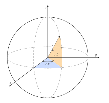
Azimuthal angles for calculating the CND and the radiation pattern, set as a vector from real values, where — this is the number of azimuth angles. The units of measurement of angles are degrees. Azimuth angles should be in the range of −180° up to 180°.
The azimuth angle is the angle between the axis and the projection of the direction vector onto the plane . When measured from the axis in the direction of the axis this angle is positive.
| Типы данных |
|
Input arguments «name-value»
Specify optional argument pairs in the format Name=Value, where Name — the name of the argument, and Value — the appropriate value. Type arguments «name-value» they should be placed after the other arguments, but the order of the pairs does not matter.
# Type — the type of radiation pattern displayed
+
"directivity" (by default) | "efield" | "power" | "powerdb"
Details
The displayed type of radiation pattern, set to one of the following values:
-
"directivity"— CND, measured in dBi; -
"efield"— directional pattern of the sensor or antenna array; for microphones, the directional pattern of the scalar sound field is displayed; -
"power"— the radiation pattern of the power of the sensor or antenna array, defined as the square of the radiation pattern; -
"powerdb"— power directional pattern, converted to dB.
| Типы данных |
|
# Elevation — corners of the place
+
[−90, 90] | a real vector of length P
Details
The angles of the place, set as a vector from real values. The angles of the location determine where the directional pattern is calculated.
| Типы данных |
|
# out — type of output data
+
:plot (by default) | :data
Details
Type of output data:
-
:plot— the function returns a graph; -
:data— the function returns data.
Output arguments
Examples
Construction of a radiation pattern of a cosine antenna
Details
Let’s set the basic parameters of the antenna elements. Let’s choose a cosine antenna as the element. Let’s build a directional diagram based on the angle of the place.
using EngeePhased

fc = 300e6 # antenna radiation frequency
c = 3e8 # signal propagation speed
freq_rng = [50e6 1000e6] # antenna frequency range

element = EngeePhased.CosineAntennaElement(FrequencyRange = freq_rng)

patternElevation(element,fc)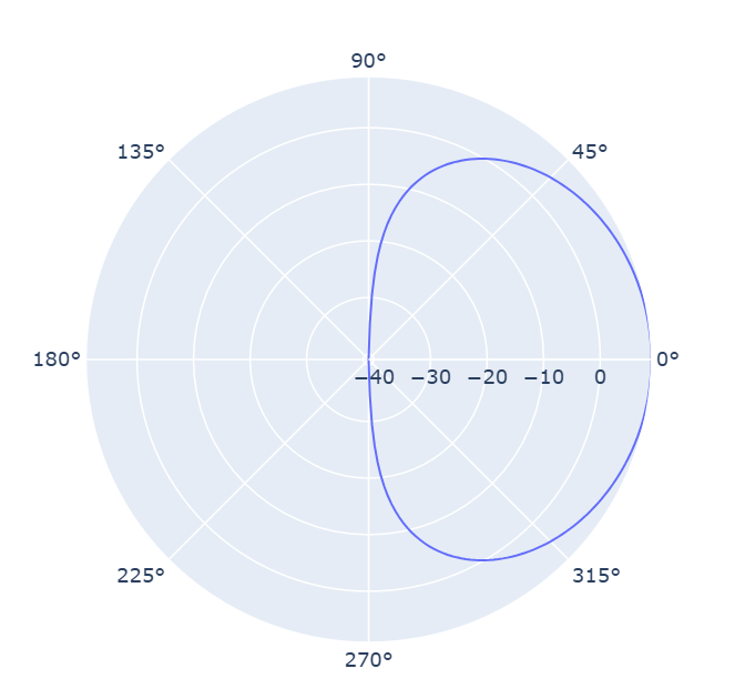
Additional Info
The coefficient of directional action
Details
The directional coefficient (CND) characterizes how directional the radiation of a sensor element or array of sensor elements is.
A higher CND is desirable when it is necessary to transmit more radiation in a certain direction. KND is the ratio of the intensity of radiation transmitted in a certain direction to the intensity of radiation transmitted by an isotropic radiator with the same total transmitted power.:
where
-
— the intensity of the transmitter radiation in the direction of ;
-
— the full power transmitted by the isotropic radiator.
For a receiving element or antenna array, the CND characterizes the sensitivity to radiation coming from a certain direction. The reciprocity principle shows that the CND of an element or antenna array during reception is equal to the directivity coefficient of the same element or antenna array during transmission. In decibels, the CND is denoted as dBi.
Azimuthal angles and location angles
Details
The azimuthal angle of a vector is the angle between the axis and its orthogonal projection onto a plane . The angle is positive when turning away from the axis to the axis . The azimuthal angles range from −180° up to 180° inclusive. The angle of a place is the angle between a vector and its orthogonal projection onto a plane. . The angle is positive if it is directed towards the positive axis. from the plane . The angles of the place range from −90° up to 90° inclusive.