pattern
Plotting directional coefficients (CND) and directional patterns of the antenna array.
| Library |
|
Syntax
Function call
-
pattern(_,Name=Value)— builds a radiation pattern of the antenna array with additional parameters specified by one or more arguments of the type «name-value».
Arguments
Input arguments
# array — phased array antenna
+
system object
Details
A phased array antenna set as a system object from the library EngeePhased.
# FREQ — frequencies for calculating the CND and radiation pattern
+
positive scalar | vector-row 1 for L real values
Details
Frequencies for calculating the CND and the radiation pattern, specified as a positive scalar or a string vector on real values. The units of frequency measurement are Hz.
-
For the antenna and microphone element
FREQmust be within the range of values specified in the FrequencyRange or FrequencyVector property of the corresponding element. Otherwise, the element does not give any response, and the CND is returned as−Inf. Most elements use the FrequencyRange property, with the exception of EngeePhased.CustomAntennaElement and EngeePhased.CustomMicrophoneElement, which use the FrequencyVector property. -
For antenna array elements
FREQIt must lie within the frequency range of the elements that make up the grid. Otherwise, the antenna array does not give any response, and the CND returns as−Inf.
| Типы данных |
|
# AZ — azimuth angles
+
[−180, 180] | a real vector of length N
Details
Azimuthal angles for calculating the CND and the radiation pattern, set as a vector from real values, where — this is the number of azimuth angles. The units of measurement of angles are degrees. Azimuth angles should be in the range of −180° up to 180°.
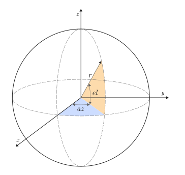
The azimuth angle is the angle between the axis and the projection of the direction vector onto the plane . When measured from the axis in the direction of the axis this angle is positive.
| Типы данных |
|
# EL — corners of the place
+
[−90, 90] | a real vector of length M
Details
The angles of the location for calculating the CND and the radiation pattern, given as a vector from real values, where — this is the number of required directions. The units of measurement of angles are degrees. The angles of the seat should be in the range of −90° up to 90°.
The angle of a place is the angle between the direction vector and the plane. . The angle of the seat is positive if measured in the direction of the axis .
| Типы данных |
|
Input arguments «name-value»
Specify optional argument pairs in the format Name=Value, where Name — the name of the argument, and Value — the appropriate value. Type arguments «name-value» they should be placed after the other arguments, but the order of the pairs does not matter.
Example: pattern(ULA_Array, fc, CoordinateSystem = "polar") builds a radiation pattern in the polar coordinate system.
# CoordinateSystem — coordinate system
+
"polar" (default) | "rectangular"
Details
The coordinate system for constructing a directional pattern, defined as "polar" or "rectangular". If CoordinateSystem it matters "polar" or "rectangular", arguments AZ and EL set the azimuth angle and the elevation angle, respectively. Values AZ must be in the range of −180° up to 180°. Values EL must be in the range of −90° up to 90°.
| Типы данных |
|
# Type — the type of radiation pattern displayed
+
"directivity" (by default) | "efield" | "power" | "powerdb"
Details
The displayed type of radiation pattern, set to one of the following values:
-
"directivity"— CND, measured in dBi. -
"efield"— radiation pattern of the sensor or antenna array. The directional pattern of the scalar sound field is displayed for microphones. -
"power"— the radiation pattern of the power of the sensor or antenna array, defined as the square of the radiation pattern. -
"powerdb"— power directional pattern, converted to dB.
| Типы данных |
|
# Orientation — orientation of the antenna array
+
[0,0,0] (by default) | A 3-by-1 column vector of real values
Details
Antenna array orientation, set as a column vector on of real values, containing three rotation angles. These three angles define orthogonal rotations relative to the axes. , and the local coordinate system. To create a complete orientation matrix, orthogonal rotations are applied in this order:
-
Rotation relative to the positive axis On the corner .
-
Rotation relative to the positive axis On the corner .
-
Rotation relative to the positive axis On the corner .
Positive angles are determined by the right-hand rule. A positive angle defines a counterclockwise rotation when looking in the positive direction of the axis, and a negative angle defines a clockwise rotation. The rule of the right hand is defined as follows: if the thumb of the right hand is directed along the positive direction of the axis, then the other fingers will bend in the direction of the positive rotation.
# Normalize — display a normalized radiation pattern
+
true (default) | false
Details
The option to display a normalized radiation pattern, set as a boolean value. Set this argument to true to display a normalized radiation pattern.
Dependencies
This argument cannot be used if for Type the value is set "directivity". The radiation pattern has already been normalized in this case.
| Типы данных |
|
# ShowLocalCoordinates — display local coordinate axes
+
true (default) | false
Details
An option for displaying local coordinate axes, set as a boolean value.
| Типы данных |
|
# ShowColorbar — display the color bar
+
true (default) | false
Details
The colorbar display option, set as a boolean value.
| Типы данных |
|
# Polarization — type of polarization
+
"combined" (by default) | "H" | "V"
Details
The type of polarization specified by one of the following values:
-
"combined"— horizontal and vertical polarizations are combined; -
"H"— only horizontal polarization is displayed; -
"V"— Only vertical polarization is displayed.
Dependencies
To use this argument, use for the argument array phased array antennas that support polarization, and then set for an argument Type meaning "efield", "power" or "powerdb".
| Типы данных |
|
# PropagationSpeed — signal propagation speed
+
1e9 (by default) | positive scalar
Details
The propagation velocity of the signal in m/s, set as a positive scalar.
| Типы данных |
|
# Weights — weight coefficients of antenna arrays
+
1 (by default) | A column vector of N by 1 complex values | a matrix of N by L complex values
Details
The weighting coefficients of the antenna arrays, set as a column vector on complex values or a matrix on complex values, where — this is the number of elements in the antenna array, and — this is the number of frequencies specified in FREQ. Weighting factors are applied to the antenna array elements to create a directional pattern and/or narrow the antenna array pattern.
Dimension Weights |
Dimension FREQ |
Appointment |
|---|---|---|
Column vector on complex values. |
Scalar or vector string on . |
Applies weights to one frequency or to all frequencies. |
The matrix on complex values. |
Vector string on . |
Applies each of the columns |
Use complex weighting factors to direct the response of the antenna array in different directions. You can create weights using the system object. EngeePhased.SteeringVector or calculate your own weight coefficients. As a rule, before using weights in any function or system object of the library EngeePhased, such as EngeePhased.Radiator or EngeePhased.Collector, Hermitian conjugation is applied. However, for functions directivity, pattern, patternAzimuth and patternElevation for any system object of the antenna array, use the control vector without coupling.
|
| Типы данных |
|
| Support for complex values |
Yes |
# ElementWeights — weight coefficients of elements of antenna sublattices
+
ones() (default) | the NSE matrix by N
Details
The weight coefficients applied to each element of the sublattice, given as a matrix on , where is the number of elements in each individual sublattice, and — the number of sublattices. Each column in ElementWeights defines the weighting coefficients for the elements in the corresponding sublattice.
Dependencies
To use this argument, set the property SubarraySteering antenna array value "Custom".
| Типы данных |
|
| Support for complex values |
Yes |
# out — type of output data
+
:plot (by default) | :data
Details
Type of output data:
-
:plot— the function returns a graph; -
:data— the function returns data.
Examples
Construction of the antenna array radiation pattern
Details
Let’s set the basic parameters of the antenna elements, and select an isotropic element as an element of the antenna array. The first most basic geometry of the antenna array is a linear equidistant antenna. Setting this geometry using the ULA system object.
using EngeePhased

fc = 300e6 # частота излучения антенны
c = 3e8 # скорость распространения сигнала
lambda = c/fc # длина волны
freq_rng = [50e6 1000e6] # частотный диапазон антенны

element = EngeePhased.IsotropicAntennaElement(
    FrequencyRange = freq_rng,
    BackBaffled=false
)

ULA_Array = EngeePhased.ULA(
    Element = element, # элемент антенной решетки
    NumElements = 10, # количество элементов
    ElementSpacing = lambda/2, # расстояние между элементами
    ArrayAxis = "z", # ориентация антенны
    Taper = 1 # весовой коэффициент
)
ULA:
Element=IsotropicAntennaElement:
FrequencyRange=[5.0e7 1.0e9]
BackBaffled=false
UseThreads=true
NumElements=10
ElementSpacing=0.5
ArrayAxis=z
Taper=1
UseThreads=trueLet’s build a radiation pattern.
pattern(ULA_Array,fc)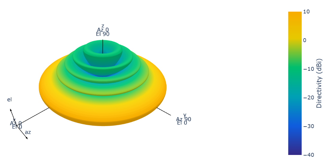
Let’s consider the second type of antenna array geometry — rectangular. Unlike the previous geometry, the antenna array has a two-dimensional structure. Let’s set such a geometry using the URA system object and construct a directional diagram.
URA_Array = EngeePhased.URA(
    # задание антенного элемента
    Element = element,
    Size=[5 5], # размер решетки
    ElementSpacing=[0.5 0.5], # расстояние между элементами
    ArrayNormal = "z",# ориентация антенны
    Taper=1 # весовой коэффициент
)

fig_ura = pattern(URA_Array,fc)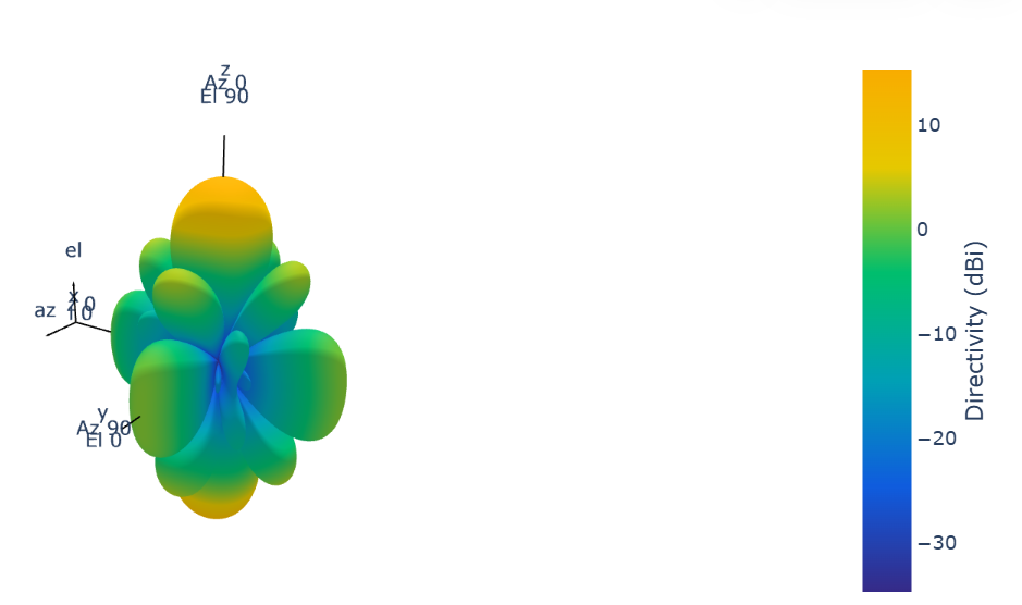
Additional Info
The coefficient of directional action
Details
The directional coefficient (CND) characterizes how directional the radiation of a sensor element or array of sensor elements is.
A higher CND is desirable when it is necessary to transmit more radiation in a certain direction. KND is the ratio of the intensity of radiation transmitted in a certain direction to the intensity of radiation transmitted by an isotropic radiator with the same total transmitted power.:
where
-
— the intensity of the transmitter radiation in the direction of ;
-
— the full power transmitted by the isotropic radiator.
For a receiving element or antenna array, the CND characterizes the sensitivity to radiation coming from a certain direction. The reciprocity principle shows that the CND of an element or antenna array used for reception is equal to the directivity coefficient of the same element or antenna array used for transmission. In decibels, the CND is denoted as dBi.
Azimuthal angles and location angles
Details
The azimuthal angle of a vector is the angle between the axis and its orthogonal projection onto a plane . The angle is positive when turning away from the axis to the axis . The azimuthal angles range from −180° up to 180° inclusive. The angle of a place is the angle between a vector and its orthogonal projection onto a plane. . The angle is positive if it is directed towards the positive axis. from the plane . The angles of the place range from −90° up to 90° inclusive.