Arduino Support Package: Analog photoresistor input
In the previous examples, digital outputs/outputs were extensively considered for the Arduino support package, in this example we will move on to working with an analog input. Using the Arduino support package, we implement in the Engee model a program for reading the signal from a photoresistor and processing incoming data to implement an illumination sensor.
Introduction
Previously, the implementation of the logic of the light sensor was modeled in a similar example for MIC 32 Амур. Here we use the support package to transfer the model to the controller automatically.
The example uses:
- Arduino Mega Debugging Board,
- breadboard,
- photoresistor (LDR) GL5516,
- 4.7 kOhm resistor (2 pcs),
- Connecting wires.
The task of the model is to calculate the illumination based on the value of the voltage drop across the current-limiting resistors in the photoresistor circuit.
Hardware part
Connect the elements as shown in the diagram below.:
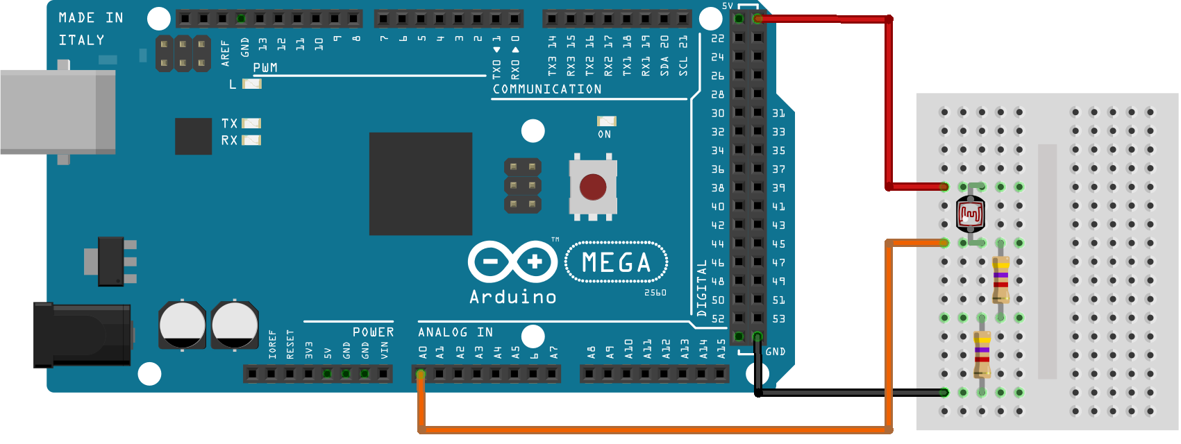
The magnitude of the voltage drop across the current-limiting resistors will be processed by the ADC at the analog input A0 of the microcontroller. The Engee model for processing the incoming signal is presented below.
The example model
The settings of the target configuration block (EDM-Target-Arduino) will remain the same as in the previous example - [LED matrix] (https://engee.com/community/ru/catalogs/projects/arduino-led-matritsa ).
In the blog, reading from the analog channel (Arduino-analogRead ) set the pin number of the analog channel used to A0 - 54.
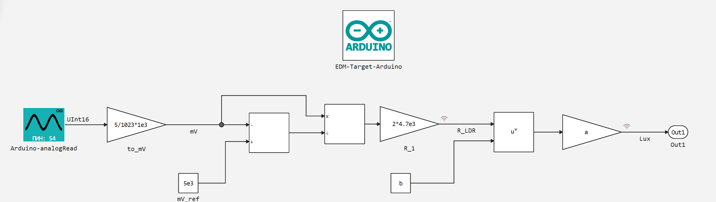
In the circuit, the resistance of the photoresistor is calculated using the simplest mathematical blocks. R_LDR based on the digital value from the ADC channel A0.
Illumination Lux in turn, it is determined by the value of the resistance of the photoresistor from the coupling function of the variables .
Function definition
The relationship between photoresistor resistance and illumination can be determined from its characteristics, for example, according to Fig.1 on page 4 of passport data.
Let's take the following central points from the characteristic area:
x_Ohm = [3e4, 7e3, 2e3];
y_Lux = [1, 10, 100];
The dependence itself can be defined as a power function of the form
where - photoresistor resistance [Ohms], - illumination [Lux], - the coefficient, - the exponent.
To optimize the function and find coefficients for previously defined characteristic points, we add the following packages:
]add LsqFit
]add Statistics
Next, let's move on to directly finding the coefficients of the function.:
using Plots; gr(format=:png)
using LsqFit, Statistics

model(x_Ohm, p) = p[1] .* x_Ohm .^ p[2]

# Initial parameters
p0 = [1e7, -1.0]

# Curve fitting
fit = curve_fit(model, x_Ohm, y_Lux, p0)

# Formula Parameters
a, b = fit.param
println("Formula: y = $a * x ^ ($b)")

# Calculation of R2
ss_res = sum((y_Lux .- model(x_Ohm, fit.param)).^2)  # the sum of the squares of the leftovers
ss_tot = sum((y_Lux .- mean(y_Lux)).^2)              # total sum of squares
r2 = 1 - ss_res/ss_tot

println("R² = $r2")
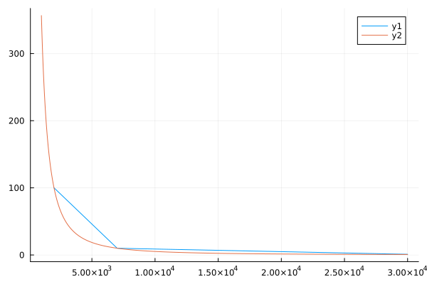
Of course, the calculation It is not necessary to adjust the function for two points. We use this estimate to make sure that the constructed curve passes through the starting points. Plot the curve and the points on the plane:
plot(x_Ohm, y_Lux)
plot!(collect(1e3:3e4), a.*collect(1e3:3e4).^b)
The coefficients obtained:
@show a;
@show b;
They are also included in the model's callbacks.
Preparation
Using this block of code, we automate the launch of the Engee server program.Integrations:
import .engee.package as epkg

const PKGNAME = "Engee-Device-Manager"

function epkg_start(pkg::String)
    if !epkg.isinstalled(pkg)
        @info "Package not installed. Installing and Starting..."
        epkg.install(pkg)
        @info "Package is up to date. Starting..."
        println("The link to connect to the server:\n"*epkg.start(pkg))
    else
        updates = epkg.checkupdates(pkg)
        if isnothing(updates)
            @info "Package is up to date. Starting..."
            println("The link to connect to the server:\n"*epkg.start(pkg))
        else
            @info "Updates available. Reinstalling and Starting..."
            epkg.update(pkg)
            @info "Package is up to date. Starting..."
            println("The link to connect to the server:\n"*epkg.start(pkg))
        end
    end
end

epkg_start(PKGNAME)
Also behind the scenes, as usual, let's launch the Engee client program.Integration and connect our device.
Model Execution
Let's run the model interactively and observe the progress of calculations of the photoresistor resistance and illumination when the brightness of the light in the room changes.
Changes in ambient brightness lead, as we can see, to corresponding changes in the calculated illumination value. Further, for the "combat" use of the developed sensor, of course, the calculated values should be correlated with the illumination values from a trusted meter.
Conclusion
In the example, as we needed, we looked at working with the digital input unit from the Arduino support package, starting with the implementation of the light sensor.