Arduino support package: digital outputs - seven-segment indicator
An example of working with multiple digital outputs of Arduino MEGA. We connect and program the operation of the seven-segment indicator 5161AS.
Introduction
In previous examples we considered working with the digital output of the Arduino. Now we will use several digital output units in Engee at once, encoding the output of sequences in the model to indicate the digits on the seven-segment indicator 5161AS.
In the example, we also use an Arduino Mega, we will also need a 330 ohm resistor, connecting wires, and a breadboard.
Hardware part
The connection diagram is shown below.
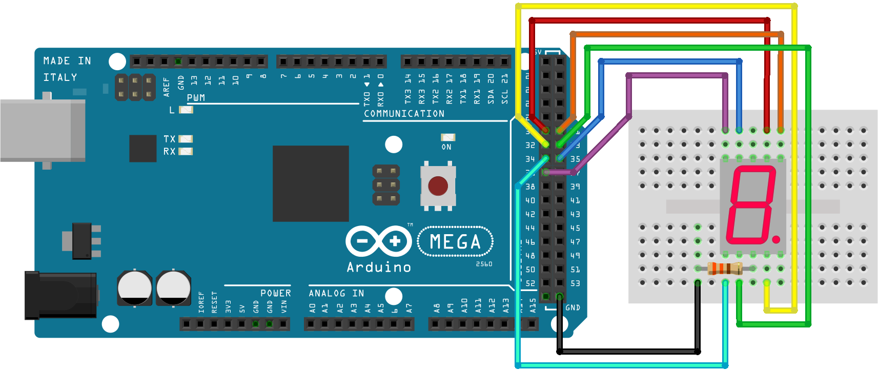
Connections are made according to the table:
|
Segment |
Contact number 5161AS |
Wire color |
Pin Arduino MEGA |
|
A |
7 |
red |
30 |
|
B |
6 |
orange |
31 |
|
C |
4 |
yellow |
32 |
|
D |
2 |
green |
33 |
|
E |
1 |
blue |
34 |
|
F |
9 |
blue |
35 |
|
G |
10 |
violet |
36 |
|
dp |
5 |
not connected |
not connected |
|
- |
8 (3) |
black |
GND |
The example model
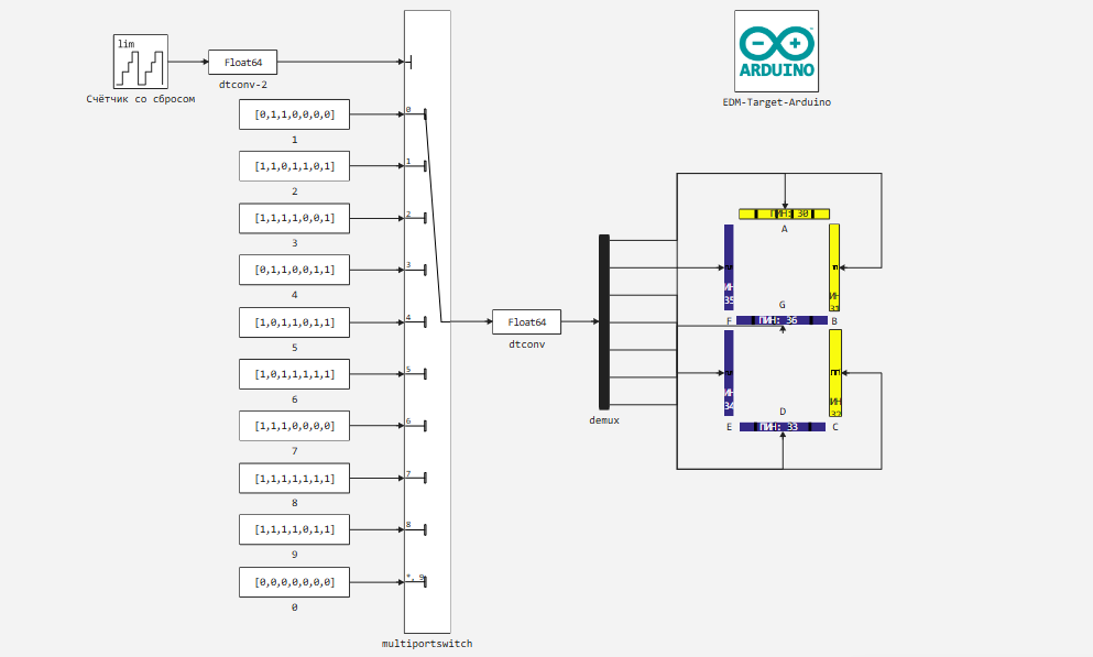
In the example model, the EDM-Target-Arduino unit has the same settings as in previous example. 7 digital signal recording units in pins 30-36 are used as the peripheral of the controller.
These blocks receive numerical values from the demultiplexer, to which the encoded sequences (blocks) are fed by the switch block. 1 - 0). The switch is controlled by a reset counter unit that sequentially changes the switch input used.
The encoded sequences of segments lit on the indicator can be determined by the following code:
]add LinearAlgebra # Installing the library to create a unit matrix
using LinearAlgebra
A,B,C,D,E,F,G = [Matrix{Int}(I, 7, 7)[:, i] for i in 1:7];
# In this row, we create a 7*7 unit matrix and use the generator (comprehension) to transfer its columns to variables.
# The sequences for including the corresponding segments in the number image are defined as follows:
one = B+C
two = A+B+G+E+D
three = A+B+G+C+D
four = F+G+B+C
five = A+F+G+C+E
six = A+F+G+E+D+C
seven = A+B+C
eight = A+B+C+D+E+F+G
nine = A+B+C+D+F+G
zero = collect(zeros(Int, 7));
Now these variables can be passed to the constants of the model, but for this example we have embedded ("coded") for clarity.
Now let's move on to running the model on Arduino.
Preparation
Using this block of code, we automate the launch of the Engee server program.Integrations:
import .engee.package as epkg

const PKGNAME = "Engee-Device-Manager"

function epkg_start(pkg::String)
    if !epkg.isinstalled(pkg)
        @info "Package not installed. Installing and Starting..."
        epkg.install(pkg)
        @info "Package is up to date. Starting..."
        println("The link to connect to the server:\n"*epkg.start(pkg))
    else
        updates = epkg.checkupdates(pkg)
        if isnothing(updates)
            @info "Package is up to date. Starting..."
            println("The link to connect to the server:\n"*epkg.start(pkg))
        else
            @info "Updates available. Reinstalling and Starting..."
            epkg.update(pkg)
            @info "Package is up to date. Starting..."
            println("The link to connect to the server:\n"*epkg.start(pkg))
        end
    end
end

epkg_start(PKGNAME)
Also behind the scenes, as usual, let's launch the Engee client program.Integration and connect our device.
Model Execution
Let's run the model interactively.
The recording shows that the logic of controlling the indicator defined in the model, as well as the display of coding sequences on it, is working correctly.
Now in Engee, using the model of this example, you can easily program the display of numbers from the Arduino.
Conclusion
In this example, we used the Arduino support package for the Engee platform element.Integration for programming the digital outputs of the microcontroller and displaying numbers on a seven-segment indicator.