Arduino Support Package: Digital outputs - LED matrix
We continue to work with the digital outputs of the Arduino - this time we will use 16 pins of the Arduino MEGA, connecting them to the 1088BS LED matrix to output binary images.
Introduction
In the previous examples, we have already looked at working with digital pins - in the example of Blink and the example with the seven-segment indicator. Using LED matrices in this example, we are following the path of increasing the dimensionality of the displayed discrete data.
We use the same Arduino MEGA microcontroller and an 8x8 1088BS LED array. You will also need 2 breadboard boards, 8 330 ohm resistors and connecting wires.
Hardware part
We will assemble the device for this example according to the connection diagram below.:
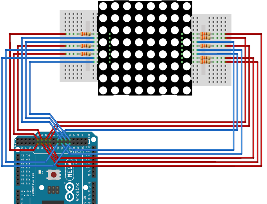
For ease of assembly, you can rely on the connection table.:
|
Contact number 1088BS |
1 |
2 |
3 |
4 |
5 |
6 |
7 |
8 |
9 |
10 |
11 |
12 |
13 |
14 |
15 |
16 |
|
Contact designation |
R5 |
R7 |
C2 |
C3 |
R8 |
C5 |
R6 |
R3 |
R1 |
C4 |
C6 |
R4 |
C1 |
R2 |
C7 |
C8 |
|
Arduino Pin Number |
34 |
36 |
41 |
42 |
37 |
44 |
35 |
32 |
30 |
43 |
45 |
33 |
40 |
31 |
46 |
47 |
Contacts with the prefix R(rows) They are responsible for supplying a line of LEDs with a set number of a high voltage level. The voltage is applied to them through current limiting resistors
Contacts with the prefix C(columns) They are responsible for supplying LEDs with a preset low voltage level number to the column.
Management features
In order for all the necessary LEDs from a given image to light up according to one measurement of the matrix, it is necessary to implement dynamic indication. In the case of an LED matrix, this means that at one time it will be possible to light the required LEDs in only one column.
Static images are thus achieved due to the high frequency of switching between columns - such switching (flickering) is no longer visible to the naked eye.
In addition, to avoid creating a blurry image when switching, it is necessary to pause between switching on the columns when the LEDs do not light up. This will allow you to withstand the required time to turn off the LEDs in the previous step.
Also, for the convenience of encoding an image, it is most convenient to use the specified row and column numbers of the matrix. This will allow us to set only the coordinates of the points, and their interpretation into a set of bits will be performed by our model.
The example model
So, in the example model:
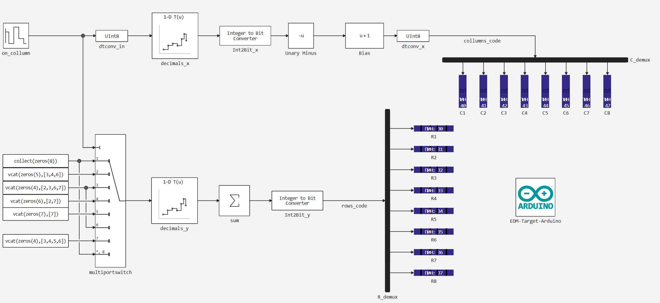
The encoding of coordinates is performed as follows:
- A vector of bits is transmitted to the digital output blocks corresponding to columns C1 - C8
columns_code(starting from the highest bit). - This vector is inverted using blocks
BiasandUnary minus, since a low voltage level is responsible for the ignition of the LED in the matrix columns. - The bit vector is calculated by the block
Integer to Bit ConvertorIn this case, the input integer is the decimal representation of the number, which is bitwise divided into the resulting vector. - This number is determined in the interpolation table according to the following vector of values:
Y = 2 .^ (7:-1:0)
also, in the interpolation table, the zero input value corresponds to the zero output value.
- For dynamic indication (sequential column switching), the block is used
on_column. It sets the value of the column to be switched on at the current step and the sampling step to determine the switching speed between the columns. - Additionally, in order for the image not to be blurred, zeros are passed between these values in the sequence of the included columns to erase all columns.
- Also, the block
on_columntransmits its values to the control input of the blockmultipirtswitchto transmit a sequence that defines the rows with the LEDs on for the current column. - Next, the selected sequence similarly passes through an interpolation table, at the output of which all the values of the output sequence are summed up. The sequence of bits is then determined, which will light or turn off the LEDs in the current column.
- This sequence is transmitted bitwise to the digital outputs of the Arduino, blocks R1 - R8.
Encoded image
The lines in which the LEDs should be lit are defined in blocks Constant at the block data inputs multiportswitch. We will set the line numbers according to the encoded image. For an 8x8 matrix, for example, the Engee platform logo can be represented in the following simplified form:
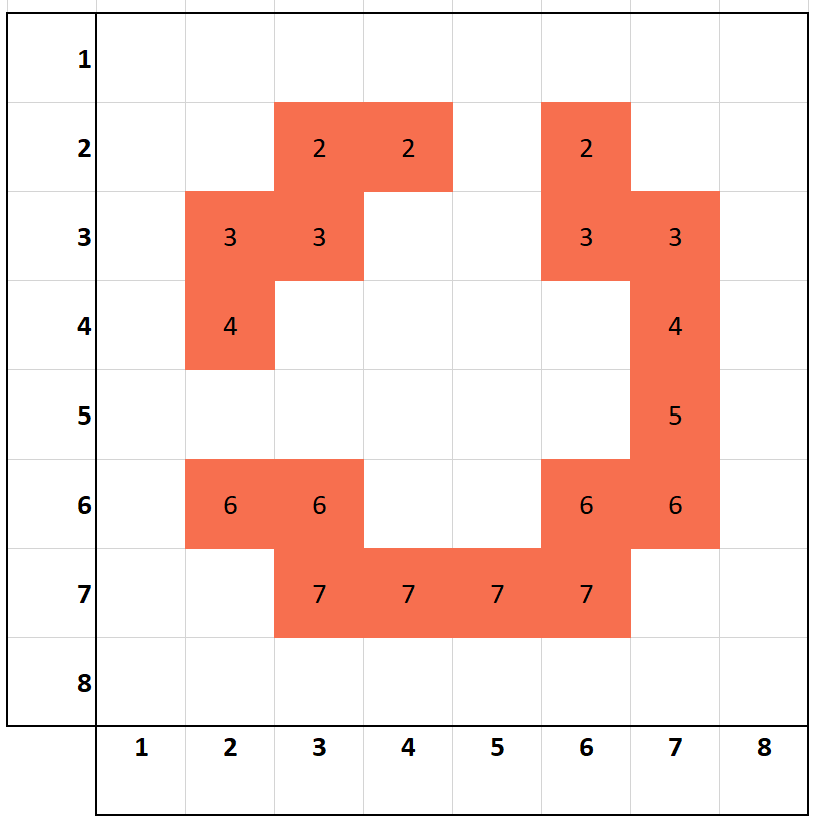
Hence, the sequence data in the rows for the blocks Constant it can be defined in this way:
Col1 = zeros(8)
Col2 = vcat(zeros(5), [3,4,6])
Col3 = vcat(zeros(4), [2,3,6,7])
Col4 = vcat(zeros(6), [2,7])
Col5 = vcat(zeros(7), [7])
Col6 = vcat(zeros(4), [2,3,6,7])
Col7 = vcat(zeros(4), [3,4,5,6])
Col8 = zeros(8);
Here, the vectors are padded with zeros to preserve the dimension of the output value. The vectors supplemented with zeros contain the row numbers in which the LED should light up for a given column.
Preparation
Using this block of code, we automate the launch of the Engee server program.Integrations:
import .engee.package as epkg

const PKGNAME = "Engee-Device-Manager"

function epkg_start(pkg::String)
    if !epkg.isinstalled(pkg)
        @info "Package not installed. Installing and Starting..."
        epkg.install(pkg)
        @info "Package is up to date. Starting..."
        println("The link to connect to the server:\n"*epkg.start(pkg))
    else
        updates = epkg.checkupdates(pkg)
        if isnothing(updates)
            @info "Package is up to date. Starting..."
            println("The link to connect to the server:\n"*epkg.start(pkg))
        else
            @info "Updates available. Reinstalling and Starting..."
            epkg.update(pkg)
            @info "Package is up to date. Starting..."
            println("The link to connect to the server:\n"*epkg.start(pkg))
        end
    end
end

epkg_start(PKGNAME)
Also behind the scenes, as usual, let's launch the Engee client program.Integration and connect our device.
Model Execution
Now let's move on to executing the model. Let's run it in independent mode, since the Arduino support package has a physical limitation in the sampling rate of the executed model due to the platform features. The sampling time limit is set at 20 ms, whereas a full-fledged dynamic display in this model requires 100 microseconds.
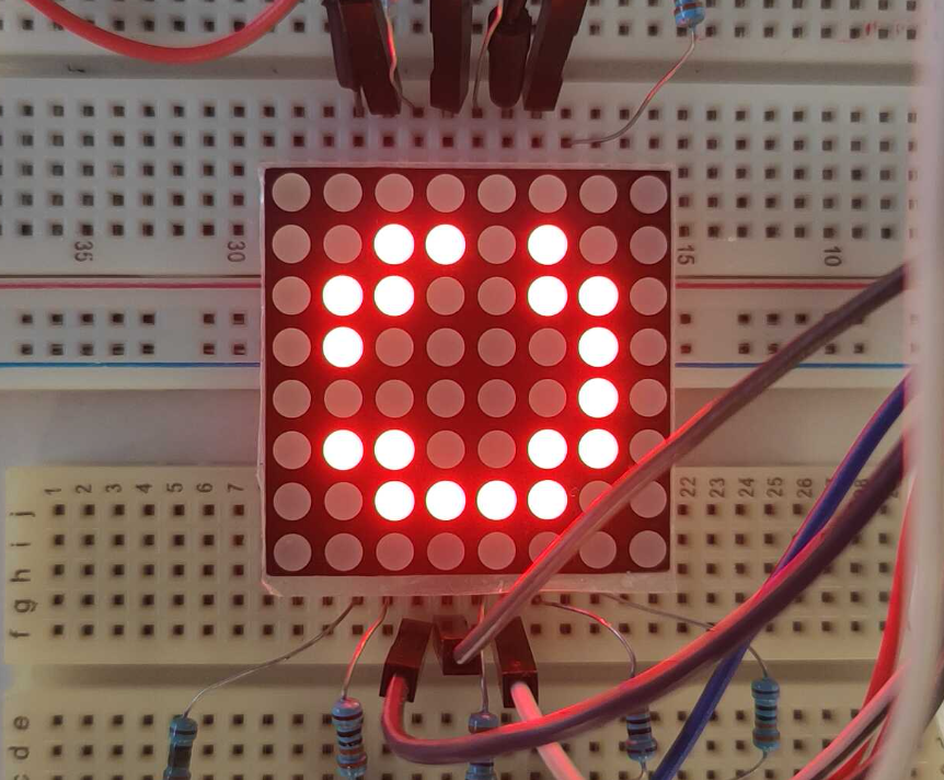
The effect of the sampling rate of the model on the static nature of the image during dynamic display is clearly visible in the recording below.
Also, the final result of the work is in the form of a static image.:
Another feature of the current model in comparison with the previous initial examples is that the ports of the Arduino peripheral blocks, as well as constants and transformations in the model, are optimized in terms of data types sufficient for operation - the type is used to the maximum. UInt8, including in blocks CFunction Arduino peripherals.
Conclusion
In this example, we were able to use even more digital outputs of the Arduino MEGA. This is how we were able to control the dynamic display on the 1088BS LED matrix with binary image output from the Engee model.