Arduino Support Package: Quick Start
The first example from the series is for getting started with Arduino microcontrollers from Engee without diving into the code. The example explains step by step how to set up the connection, build and run your first model on the controller.
Introduction
The automated transfer of the Engee model to embedded systems (including Arduino) has been implemented for a long time. In early projects, you can find several basic examples of transferring a model to code and executing it on an Arduino with varying degrees of user immersion in low-level programming. Such examples primarily serve as instructions for mastering scenarios for transferring a model to embedded systems. Here are the scenarios that were covered earlier:
- "Algorithm Export" (example) :
- the user develops the algorithm in the model
- the C code is generated automatically from the model
- the user downloads files
- files are added to the project in an external IDE
- the user integrates the algorithm code and the microcontroller peripheral code
- the user programs the controller
- "Peripheral units" (example):
- the user develops an algorithm in the model
- the user transfers the peripheral code
- the C code is generated automatically from the model
- the user downloads files
- files are added to the project in an external IDE
- the user programs the controller
Such scenarios are convenient when the user is not ready to abandon the Toolchain already used for embedded systems, and Engee is used to develop an algorithm in a model or automatically integrate the algorithm and peripheral code.
To avoid immersion in the C code, Engee users can use embedded system support packages. They're opening up [two completely new scenarios] (https://engee.com/helpcenter/stable/en/engee-hardware/target-hardware.html ):
- "Independent execution"
- the user develops an algorithm in the model
- The user adds specialized blocks from the microcontroller support package
- Controller programming starts automatically
- "Interactive execution"
- the user develops an algorithm in the model
- The user adds specialized blocks from the microcontroller support package
- Controller programming starts automatically
- The user can control the model running on the microcontroller, change its parameters and visualize the model signals.
Preparation and operation of these scenarios on Arduino microcontroller and will be covered further.
Step 1: Arduino and its Toolchain
For this example, we will need:
- Arduino microcontroller (Uno, Mega or other with AVR chip)
- USB cable
- The microcontroller drivers installed on the PC
- Toolchain Arduino - ArduinoCLI
Connect the Arduino to the PC, make sure that the drivers are installed, and the PC recognizes the microcontroller. At this stage, we will immediately determine the port to which our microcontroller is connected.:
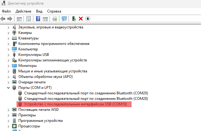
In our case, this is the Arduno Uno R3, on the COM10 port.
Download ArduinoCLI - in the future, this tool will be called from Engee automatically to program the microcontroller. It will be most convenient to place it in a specific directory. In the case of this and subsequent examples, its path is defined as "D:\targets\arduino-cli.exe". Let's remember it for future reference.
We will get the full name of our board using ArduinoCLI. To do this, go to its directory, open a terminal in it and call, for example, the command in PowerShell .\arduino-cli.exe board list
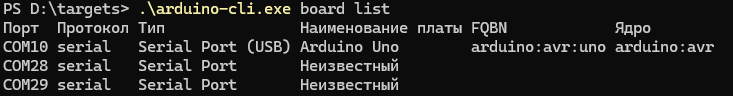
This way we will get a list of COM-connected devices. It can be seen from the command line output that an Arduino Uno board with the full name (FBQN) is connected to the COM10 arduino:avr:uno - we will also need it further.
The available FQBNS can be obtained, for example, by calling the command
.\arduino-cli.exe board listall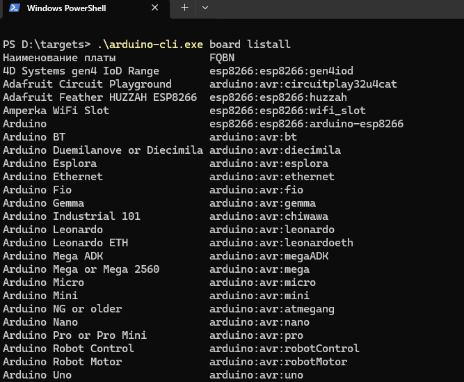
Step 2: The Engee platform.Integrations
The connection between the target device and the PC is established, now establish connection between Engee and PC. To do this, we will need:
- Install Engee.Интеграции
# engee.package.install("Engee-Device-Manager")
-
Download the archive from the client program, unzip and run it. In the case of this example, the client program is conveniently located in the same directory as ArduinoCLI.:
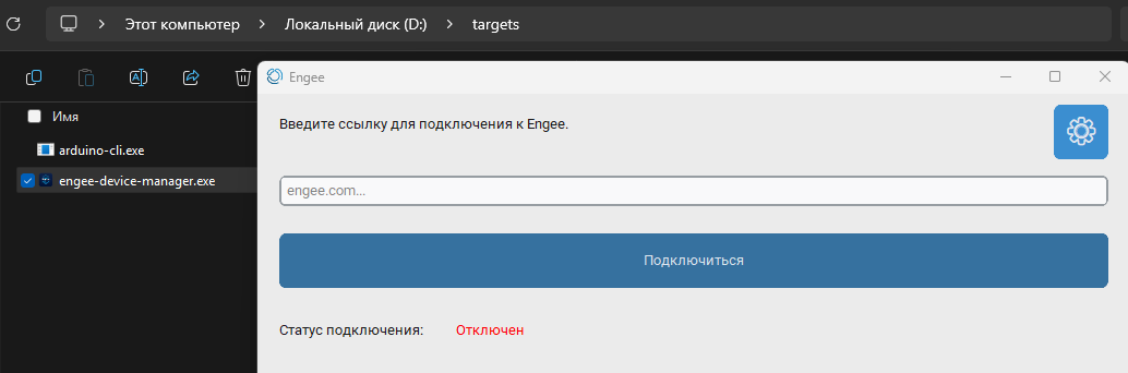
- Establish a connection between Engee and PC. You need to insert the previously received link into the client program and click Connect:
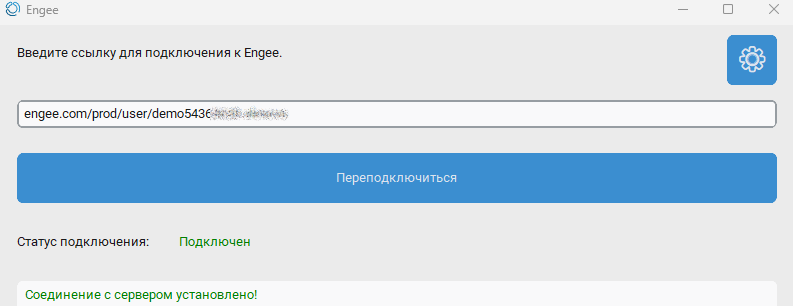
The connection between the PC and Engee is established, you can proceed directly to the development of the model and programming of the microcontroller.
In addition, if you want, you can get/update the [examples folder](https://engee.com/helpcenter/stable/en/feature/engee-package-functions.html#engee.package .getdemos), where you can find test cases for working with external devices, peripherals, and microcontrollers.
engee.package.getdemos("Engee-Device-Manager")
Step 3: The Example Model
An example of "Hello World!" for Arduino, this is an LED flashing program. This is how it will look in the Engee model:
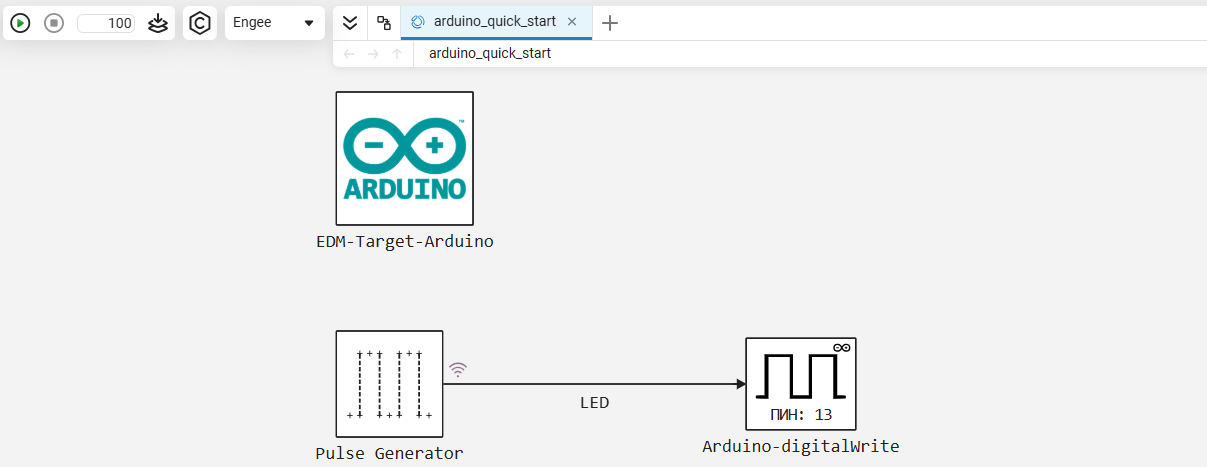
The algorithm of the model consists of one block, the Pulse Generator. Its settings:
Pulse type - Based on calculation steps; Amplitude - 1; Period (number of calculation steps) - 50; Pulse width (number of calculation steps) - 25; Delay before the first pulse (number of calculation steps) - 0, Sampling period - 0.02.
The block forms a meander with a frequency of 1 Hz and D = 50%.
The signal LED At the output of the block, it is transmitted to the controller's peripheral unit. Arduino-digitalWrite is the digital output of GPIO 13. At each step of the model calculation, the block invokes the standard function of writing to the digital output digitalWrite() from the Arduino library.
Pin 13 is the output to which the built-in LED on the debugging board is connected.
The [EDM-Target-Arduino] block(https://engee.com/helpcenter/stable/en/hardware-arduino/edm-target-arduino.html ) is necessary to establish communication with the microcontroller and its Toolchain. This is how the block settings are defined in the current example:
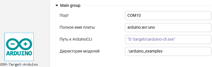
- Port is the name of the serial port to which our microcontroller is connected. It can be defined as follows:
COM10- for Windows, this is the value we got for the microcontroller in our example./dev/tty/USB0- an example of a serial port name for Linux.<auto>- if one microcontroller is connected, Engee will determine its port independently.
- The full name of the board is the FQBN of the board that we received earlier. There are possible options here:
arduino:avr:uno/arduino:avr:mega/arduino:avr:leonardo/ ... - depending on which card is connected.<auto>- if one microcontroller is connected, Engee will determine its name on its own.
- Path to ArduinoCLI - full path to ArduinoCLI
"D:\targets\arduino-cli.exe"- we copied this value in the context menu of Windows Explorer in our example."D:\targets\arduino-cli"/D:\targets\arduino-cli.exe/D:\targets\arduino-cli- also acceptable options for specifying a path in Windowa/home/Targets/Arduino/arduino-cli- option for specifying the path to ArduinoCLI in Linux<auto>- in this case, Engee will automatically search for ArduinoCLI according to the following priorities:- paths added to the environment variable
PATH;
- paths added to the environment variable
- the current directory of the client program;
C:\Program Files\;C:\Program Files (x86)\.
- Directory of models - the path for the location of the folder with the sketch
.inothe models are relative to the location of the client program. In our example, this is.\arduino_examples, this folder will be created automatically, and the final folder structuretargetsthis example will look like this:
PS D:\targets> tree /f
Структура папок
Серийный номер тома: 4040-B539
D:.
│   arduino-cli.exe
│   engee-device-manager.exe
│
└───arduino_examples
    └───arduino_quick_start
            arduino_quick_start.ino
Step 4: Modeling
The example model is assembled and, before uploading it to the microcontroller, of course, it must be tested by modeling in Engee. This can be done both in the graphical interface and automated in a script using [software management]. моделированием](https://engee.com/helpcenter/stable/en/modeling/programmatic-modeling-simulation.html).
cd(@__DIR__)
name = "arduino_quick_start"
try
    engee.close(name, force=true) # closing the model
catch err # if there is no model to close and engee.close() is not executed, it will be loaded after catch.
    m = engee.load(name*".engee") # loading the model
end;
try
    engee.run(m) # launching the model
catch err # if the model is not loaded and engee.run() is not executed, the bottom two lines after catch will be executed.
    m = engee.load(name*".engee") # loading the model
    engee.run(m) # launching the model
end
During the simulation, the result of the simulation was obtained with the recording of the "LED" signal in the workspace. We will get the time and value of the signal, and plot its graph for visual verification of the algorithm's operation.:
data = collect(simout[name*"/LED"])
t = data.time
LED = data.value

gr(format=:png)

plot(t, LED; label = :none)
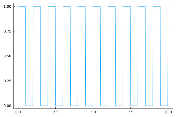
The graph shows a meander with a frequency of 1 Hz, D = 50% and amplitude = 1. The simulation stage in Engee has been completed successfully, blocks from the support package have been added, and a connection to the microcontroller has been established. Now you can proceed to the execution of the model according to the two planned scenarios.
Step 5: Independent Execution
First of all, we will switch the target platform: instead of Engee in the drop-down list, select Target Hardware:
Click on the ** button"Запуск в независимом режиме"**. This will result in a standalone real-time application being generated and running on the target platform independently of Engee. Information about the assembly and loading of the model is visible in the diagnostic window.
During the model assembly process, you can observe how Engee automatically launches ArduinoCLI to build the project, compile it, and upload it to the microcontroller. The flashing of the RX/TX LEDs on the Arduino board also indicates the progress of the boot process. The blinking of the L LED on the board indicates that the model has been completed.
Running in this mode on an Arduino causes the real-time application generated from the model to run on the microcontroller independently of Engee. After launching the application in Engee, we only see information about the time spent on code generation and uploading to the device, as well as a notification about the launch of the model.
Step 6: Interactive Execution
In interactive режиме implemented two-way data exchange between Target Hardware and Engee. To run the model in this mode, click on the ** button."Run the model on hardware"** - an ArduinoCLI call also occurs, the application loads, and the corresponding messages are displayed in the model diagnostic window.
However, immediately after launching the application, you can see that the model is running on an Arduino, and the signal change is shown on the graphs in Engee. The data transfer from the microcontroller to Engee is indicated by the periodic flashing of the TX LED on the board, and graphs of recorded signals can be observed in the signal visualization window.
In addition, it remains possible to control the application on the Arduino - at the right moment, for example, you can stop the execution of the model on the hardware.
For the convenience of monitoring the model, you can increase the time - in this mode, the model runs for 100 seconds instead of 10 seconds. For unlimited execution time, you can enter in the line at the end of the simulation interval
Inf.
Another interesting and important feature of working in this mode is changing the model parameters on the fly. This is described in more detail in [the continuing example] (https://engee.com/community/ru/catalogs/projects/arduino-meniaem-parametry-na-letu ).
Addition: Data Inspector
Another convenient tool for monitoring data received from Arduino is the built-in Engee application "Инспектор данных". Open the application interactively:
Thanks to this tool, it becomes possible to analyze signals on various runs of the model, even during its execution.
Addendum: The results of the support package
Additionally, you can pay attention to the results of the support package. After starting the independent/interactive mode, a code is generated from the model, which Engee places in the folder /user/codegen_target/ the file browser. We will get the name and contents of the most recently created folder:
path = "/user/codegen_target"
folders = filter(f -> isdir(joinpath(path, f)), readdir(path))
if !isempty(folders)
    latest_folder = last(sort(folders, by=f -> stat(joinpath(path, f)).ctime))
    println("Last created folder: \n"*latest_folder)
end
println("\Other content:")
readdir(joinpath(path,latest_folder)) .|> println;
In this folder:
- .h, .c files are the model code in C, which can be downloaded and used in the code export script.
- the codeinfo file.json is a description of the model code interfaces in JSON format. The names of functions, data structures, states, configurable parameters, and model metadata are provided here.
Here is what the contents of this file are in our case.:
for line in eachline(joinpath(path,latest_folder,"codeinfo.json"))
    println(line)
end
The source files of the application generated using ArduinoCLI can be found in the directory along the path:
C:\Users\<username>\AppData\Local\arduino\sketches\<sketch_id> - there will be the same files as in the folder. /user/codegen_target/ the Engee file browser.
The path "Model Directory", which we previously set in the "EDM-Target-Arduino" block, will now contain the folder
D:\targets\arduino_examples\arduino_quick_start, containing a sketch of the example arduino_quick_start.ino.
Conclusion
In this example, we have mastered getting started with the Arduino support package in Engee: we have gone through the steps in the process of establishing a connection, preparing the environment, developing a model, and executing the model in independent and interactive modes on Arduino.