The Finite State Machine debugger
Creating models based on finite automata is an effective way to describe complex discrete logic. To simplify the analysis of the operation of such machines and ensure control over their behavior, Engee provides a built-in debugger that allows step-by-step monitoring of the execution to identify errors in the finite state machine.
The debugger is available inside the block Chart and it is enabled if for states  and/or transition
  set a breakpoint:
Breakpoint They look like red markers.  (or grey
  if disabled).
Breakpoint — a key tool of the finite state machine debugger, with which you can set conditions for stopping the execution of the model. This allows us to investigate the behavior of the model at a specific step in the execution of a finite automaton. So, using breakpoints, you can:
-
Step-by-step control of the finite state machine simulation;
-
View variable values at a specific step;
-
Analyze when and which states become active or terminate;
-
Check whether the following are being performed Groups of state machine operators (for entry, during, and exit groups);
-
Analyze the validity of transitions, including transitions with operators temporal logic, signal edge tracking and indicators of changes;
-
As well as diagnose hidden logical errors and unstable states that do not appear in the output of the model.
Working with breakpoints
Breakpoint can be set to:
-
State
— when entering, during execution and when exiting; -
Transition
— when checking a condition or before making a transition.
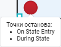
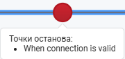
To add a breakpoint to the state or a transition left-click on the desired element and then on the breakpoint icon that appears. The active breakpoint will be marked with a red marker.:
|
|
You can set different types of breakpoints for states and transitions. To do this, click on the breakpoint with the left mouse button:
In the states |
At the crossings |
|
|
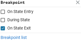
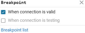
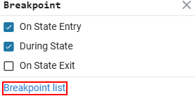
The selected types will be displayed when the cursor hovers over the breakpoint.:
You can enable any combination of checkboxes, depending on which point of the state/transition you want to track. If you uncheck all the boxes, the breakpoint will be deleted.
To temporarily disable the breakpoint (leaving it on the status/transition, but not triggered), click on the breakpoint icon again.:
List of breakpoints
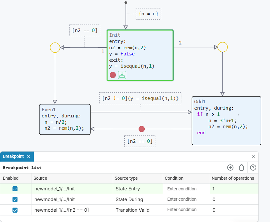
To go to the list of breakpoints, left-click on the already created breakpoint and select Breakpoints list:
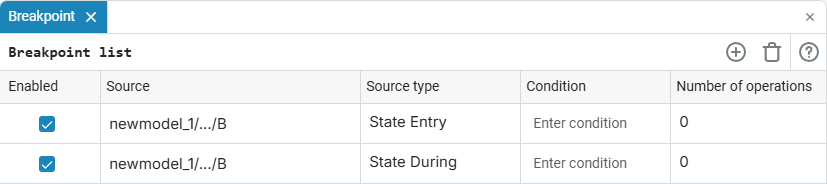
This will open a list of all breakpoints of the finite state machine model.:
Through the list of breakpoints, you can:
-
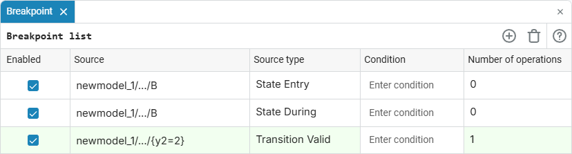
Track which breakpoints were triggered during the simulation of the model and the number of their triggers. The number of triggers is shown in the column "Number of operations". The triggered breakpoint will be highlighted in green:
-
Delete a breakpoint by left-clicking on it in the list and clicking on the icon Remove breakpoint
 .
. -
Add a breakpoint by left-clicking on it in the list and clicking on the icon Add Breakpoint:
 . In the window that opens, select the necessary parameters — the type of trigger and, if necessary, the condition:
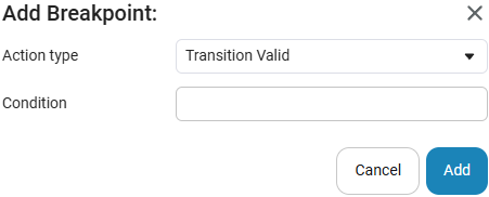
-
Enable/disable a breakpoint by using the check boxes.
 at the corresponding points.
 -
Set a condition for a breakpoint by entering an expression in the column "Condition" opposite the desired line. For example,
y > 5or(y == 0) & (n > 5). The conditions can specify logical expressions supported by the logic of finite automata. They use the values of the inputs, outputs, and all variables available in the Chart block.
Managing model execution
| Step-by-step execution is available only inside the Chart block and does not affect the global execution of the model in the workspace. When exiting the Chart block, the panel disappears and Engee returns to the normal simulation mode. |
After setting the first breakpoint inside the Chart block, a step-by-step simulation control panel will appear in the upper-left corner of the canvas.:

Three execution control commands are available:
-
Step in — proceeds to the next stage of execution inside the current state or transition. The command executes the details of the finite state machine element step by step. It can be:
-
Input to the finite state machine diagram;
-
Checking the transition conditions;
-
Performing transition actions;
-
State Activation;
-
Executing groups of operators
entry,duringorexit; -
Transition to child states or nested Transition graphs.
-
-
Step over — performs the current step in its entirety, without going to the internal details. The command is used to sequence the key execution steps of a finite state machine.:
-
Activating a finite state machine;
-
Transition to the state;
-
Checking available traffic;
-
Performing transition actions;
-
Performing status actions.
-
-
Step out — completes the execution of the current state, transition, child state, or nested transition graph and returns to the higher level of execution. The command allows you to exit the current nesting level and continue executing the machine at the level from which the input was performed.
To visually track the current stage of the machine model execution, a backlight is used — the active element is highlighted in green when executed both in the model itself and in the list of breakpoints.:
In addition to highlighting with color, the system also provides hints in the form of icons, which, when you hover the cursor over them, pop up an auxiliary message about how exactly the model worked in the current step.:
-
 Before entering
 -
 During
 -
 Before exit
 -
 Before testing transition
 -
 Before taking transition
Viewing and editing variables
During a step-by-step simulation of a finite automaton, you can not only observe which states and transitions are activated, but also monitor the values of variables used inside the Chart block.
To do this, open settings window ![]() The Chart block — it displays all available variables.
The Chart block — it displays all available variables.
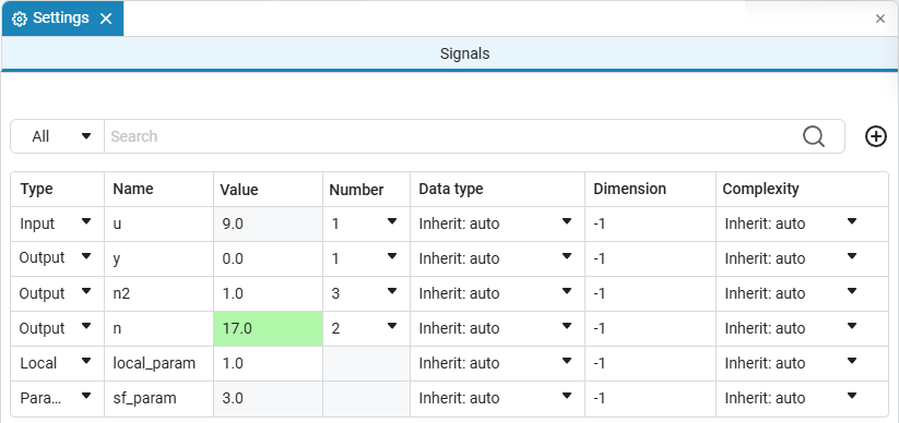
In this window you can:
-
View the current values of variables at each step;
-
To see changes in values — they are highlighted in green, similar to the list of breakpoints.;
-
Manually change the values of some variables right when the model is stopped.
Variable values can only be edited during the simulation pause and when there is an active breakpoint.
To change the value of a variable:
-
Move the cursor to the desired row in the column "Value»;
-
Click on the current value;
-
Enter a new value and press Enter.
| You can change local variables and output signals. The values of the input signals are set from the external modeling environment (outside the Chart block). |