Transmission Line
A section of a three-phase power transmission line with concentrated parameters.
blockType: AcausalElectricPowerSystems.Passive.Lines.Transmission
|
Path in the library: |

Description
Block Transmission Line allows you to simulate one of the following power line models:
-
Lumped parameter L-section— a series of sequentially connected L-segments (L-shaped substitution scheme). -
Lumped parameter pi-section— a series of sequentially connected U-segments (U-shaped substitution scheme).
L-shaped substitution scheme
The following block diagram shows a model of one L-shaped segment of a power line.
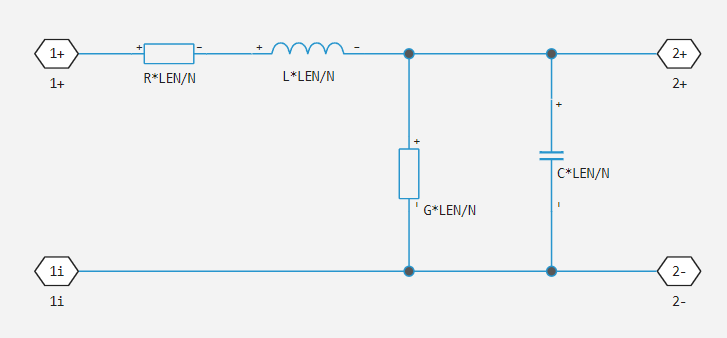
The block uses copies of the above segment model connected in series.
The parameters are as follows:
-
— line resistance per unit length.
-
— line inductance per unit length.
-
— line capacity per unit length.
-
— line conductivity per unit length.
-
— the length of the line.
-
— the number of consecutive segments.
U-shaped substitution scheme
The following block diagram shows a model of a single U-shaped segment of a power line.
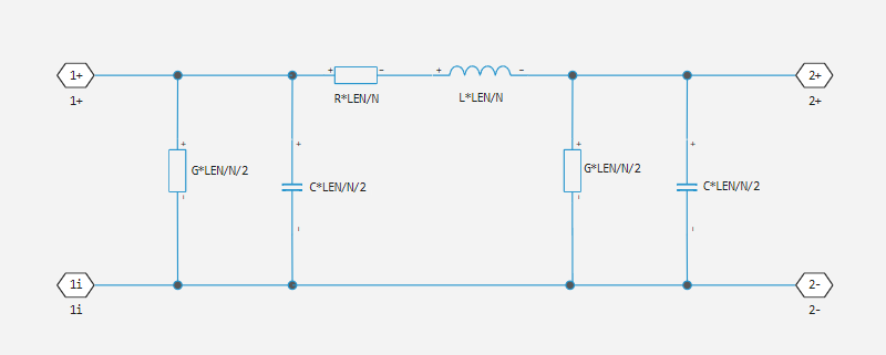
The block uses copies of such a segment model connected in series. The parameters are determined in the same way as for the L-shaped substitution scheme. Unlike the L-shaped segment model, the U-shaped segment model is symmetrical.
Parameterization of a line with concentrated parameters
Cable manufacturers usually do not specify the value of the inductance per unit length, but instead indicate the impedance value. The inductance, capacitance, and impedance index are related as follows:
The block allows you to specify or when using a model with concentrated parameters.
Assumptions and limitations
-
It is recommended to use a trapezoidal solver, for example
ImplicitEuler. This is due to the fact that power line models with lumped parameters have very weakly damped internal dynamics, which is best suited for trapezoidal solvers to ensure numerical accuracy. -
Model
Lumped parameter pi-sectionIt has a parallel capacitor at both ends. This means that it cannot be connected directly to an ideal voltage source, that is, a source without internal resistance. -
Model
Lumped parameter L-sectionIt has a serial input resistor, so it can be connected directly to an ideal voltage source.
Ports
The location of the ports is shown in the figure:

Non-directional
p1 — internal conductor 1
electricity
An electrical port connected to one end of the internal conductor of a power transmission line.
n1 — external shielding conductor 1
electricity
An electrical port connected to one end of an external shielding conductor of a power transmission line.
p2 — internal conductor 2
electricity
An electrical port connected to one end of the internal conductor of a power transmission line.
n2 — external shielding conductor 2
electricity
An electrical port connected to one end of an external shielding conductor of a power transmission line.
Parameters
Model Type — type of power line model
Lumped parameter L-section | Lumped parameter pi-section
Choose one of the following power line models:
-
Lumped parameter L-section— modeling of a power transmission line as a series of sequentially connected G-segments. -
Lumped parameter pi-section— modeling of a power transmission line as a series of pi segments connected in series.
Parameterization — parameterization of the pass model:q[<br>] By characteristic impedance and capacitance (by default) | By inductance and capacitance
Select the parameterization method of the model:
-
By characteristic impedance and capacitance— specify the values of the Characteristic impedance and Capacity per unit length parameters. This is the default method. -
By inductance and capacitance— specify the values for the parameters Inductance per unit length and Capacity per unit length.
Dependencies
This parameter is used only when selecting a value. Lumped parameter L-section or Lumped parameter pi-section for the Model type parameter.
Characteristic impedance — pass impedance indicator:q[<br>] 50 Ohms (default) | positive scalar
The indicator of the impedance of the power transmission line. The parameter value must be greater than zero.
Dependencies
This option is used only when selecting By characteristic impedance and capacitance for the Parameterization parameter.
Frequency used for rlcg specification — the frequency for which the RLC parameters pass are set:q[<br>] 50.0 Hz (default)
The frequency for which the parameters are set , , , , where:
-
— line resistance per unit length.
-
— line inductance per unit length.
-
— line capacity per unit length.
-
— line conductivity per unit length.
Inductance per unit length — inductance per unit length
220 mcg/m (default) | positive scalar
The effective inductance of a power transmission line per unit length. The parameter value must be greater than zero.
Dependencies
This parameter is used only when selecting a value. Lumped parameter L-section or Lumped parameter pi-section for the Model type parameter and By characteristic impedance and capacitance for the Parameterization parameter.
Capacity per unit length — capacity per unit length
90 pF/m (default)
The capacity of the power transmission line per unit length.
Dependencies
This parameter is used only when selecting a value. Lumped parameter L-section or Lumped parameter pi-section for the Model type parameter.
Resistance per unit length — resistance per unit length of
0.3 Ohms/m (default)
The total resistance of a power transmission line (i.e. the sum of the resistances of two conductive paths) per unit length.
Dependencies
This parameter is used only when selecting a value. Lumped parameter L-section or Lumped parameter pi-section for the Model type parameter.
Insulation conductivity per unit length — insulation conductivity per unit length
5e-6cm/m (default) | a non-negative scalar
The conductivity between two wires of a power line per unit length. The parameter value must be greater than or equal to zero.
Dependencies
This parameter is used only when selecting a value. Lumped parameter L-section or Lumped parameter pi-section for the Model type parameter.
Line length, km — length of the power transmission line
1.0 km (default)
The length of the power transmission line. The parameter value must be greater than zero.
Number of segments — number of segments of the pass model:q[<br>] 1 (default)
The number of model segments used to represent the power line. The parameter value must be an integer greater than or equal to 1.