Three-Phase PI Section Line
A section of a three-phase power transmission line with concentrated parameters.
blockType: AcausalElectricPowerSystems.Passive.Lines.ThreePhaseTransmissionSPS
|
Path in the library: |

Description
Block Three-Phase PI Section Line It is a balanced three-phase power transmission line according to a U-shaped substitution scheme.
Unlike the linear model with distributed parameters, in which resistance, inductance, and capacitance are evenly distributed along the line, the block Three-Phase PI Section Line combines the line parameters into one U-shaped section, as shown in the figure below.
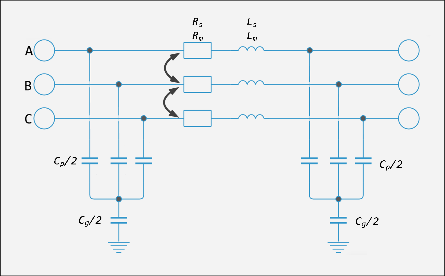
Line Parameters , and They are set as parameters of the forward and zero sequence, which take into account the inductive and capacitive connections between three-phase conductors, as well as the grounding parameters. This method of setting line parameters assumes that the three phases are balanced.
Own and mutual resistance ( , ), self and mutual inductors ( , ) three connected inductors, as well as phase capacitances and grounding capacitances They are derived from the RLC parameters of the direct and null sequence as follows.
As an example, let’s take the following line parameters:
, |
Resistances of the forward and zero sequences per unit length |
, |
Inductance of direct and zero sequences per unit length |
, |
Capacities of the forward and zero sequences per unit length |
|
Frequency |
|
Length of the line section |
The general parameters are evaluated first direct and null sequences, including hyperbolic corrections:
where , , , , , — hyperbolic correction factors of the forward and zero sequence.
For a short section of the line (approximately km) these correction factors are insignificant (close to unity). However, for long lines, these hyperbolic corrections must be taken into account in order to obtain an accurate model of the line with the specified frequency.
Then the RLC parameters of the line section are calculated as follows:
Parameters
Main
#
Parameterization —
the method of setting line parameters
Sequence impedance | Sequence impedance (R, X, B)
Details
The line parameters are set in the following way:
-
Sequence impedance— set the active resistance, inductance and transverse capacitance ( , , ) for the forward and zero sequences; -
Sequence impedance (R, X, B)— set the active resistance, inductive resistance and capacitive conductivity ( , , ) for the forward and zero sequences.
| Values |
|
| Default value |
|
| Program usage name |
|
| Evaluatable |
No |
#
Line length —
length of the power transmission line
m | um | mm | cm | km | in | ft | yd | mi | nmi
Details
The length of the power transmission line.
| Units |
|
| Default value |
|
| Program usage name |
|
| Evaluatable |
Yes |
#
Frequency used for rlc specification —
the frequency for which the RLC or RXB parameters are set
Hz | kHz | MHz | GHz
Details
At a given frequency, the transmission line parameters are adjusted to more accurately represent the resistances of the forward and zero sequences.
| Units |
|
| Default value |
|
| Program usage name |
|
| Evaluatable |
Yes |
#
Positive-sequence resistance —
active linear resistance of the forward sequence
Ohm/m | GOhm/m | MOhm/m | kOhm/m | mOhm/m | Ohm/km
Details
Active linear resistance of the forward sequence.
| Units |
|
| Default value |
|
| Program usage name |
|
| Evaluatable |
Yes |
#
Zero-sequence resistance —
active linear resistance of the zero sequence
Ohm/m | GOhm/m | MOhm/m | kOhm/m | mOhm/m | Ohm/km
Details
Active linear resistance of the zero sequence.
| Units |
|
| Default value |
|
| Program usage name |
|
| Evaluatable |
Yes |
#
Positive-sequence inductance —
specific inductance of the direct sequence
H/m | mH/m | nH/m | uH/m | H/km | mH/km
Details
The specific inductance of the direct sequence.
Dependencies
To use this parameter, set for the parameter Parameterization meaning Sequence impedance.
| Units |
|
| Default value |
|
| Program usage name |
|
| Evaluatable |
Yes |
#
Zero-sequence inductance —
specific inductance of the zero sequence
H/m | mH/m | nH/m | uH/m | H/km | mH/km
Details
The specific inductance of the zero sequence.
Dependencies
To use this parameter, set for the parameter Parameterization meaning Sequence impedance.
| Units |
|
| Default value |
|
| Program usage name |
|
| Evaluatable |
Yes |
#
Positive-sequence reactance —
linear inductive resistance of the direct sequence
Ohm/m | GOhm/m | MOhm/m | kOhm/m | mOhm/m | Ohm/km
Details
Linear inductive resistance of the direct sequence. This value must be greater than zero.
Dependencies
To use this parameter, set for the parameter Parameterization meaning Sequence impedance (R, X, B).
| Units |
|
| Default value |
|
| Program usage name |
|
| Evaluatable |
Yes |
#
Zero-sequence reactance —
linear inductive resistance of the zero sequence
Ohm/m | GOhm/m | MOhm/m | kOhm/m | mOhm/m | Ohm/km
Details
Linear inductive resistance of the zero sequence. This value must be greater than zero.
Dependencies
To use this parameter, set for the parameter Parameterization meaning Sequence impedance (R, X, B).
| Units |
|
| Default value |
|
| Program usage name |
|
| Evaluatable |
Yes |
#
Positive-sequence capacitance —
specific capacity of the direct sequence
mF/m | nF/m | pF/m | uF/m | F/km | uF/km
Details
The specific capacity of the direct sequence. This value must be greater than zero.
Dependencies
To use this parameter, set for the parameter Parameterization meaning Sequence impedance.
| Units |
|
| Default value |
|
| Program usage name |
|
| Evaluatable |
Yes |
#
Zero-sequence capacitance —
specific capacity of the zero sequence
mF/m | nF/m | pF/m | uF/m | F/km | uF/km
Details
The specific capacity of the zero sequence. This value must be greater than zero.
Dependencies
To use this parameter, set for the parameter Parameterization meaning Sequence impedance.
| Units |
|
| Default value |
|
| Program usage name |
|
| Evaluatable |
Yes |
#
Positive-sequence capacitive conductance —
specific capacitive conductivity of the direct sequence
S/m | pS/m | nS/m | uS/km | uS/m | mS/m
Details
The specific capacitive conductivity of the direct sequence. This value must be greater than or equal to zero.
Dependencies
To use this parameter, set for the parameter Parameterization meaning Sequence impedance (R, X, B).
| Units |
|
| Default value |
|
| Program usage name |
|
| Evaluatable |
Yes |
#
Zero-sequence capacitive conductance —
specific capacitive conductivity of the zero sequence
S/m | pS/m | nS/m | uS/km | uS/m | mS/m
Details
The specific capacitive conductivity of the zero sequence. This value must be greater than zero.
Dependencies
To use this parameter, set for the parameter Parameterization meaning Sequence impedance (R, X, B).
| Units |
|
| Default value |
|
| Program usage name |
|
| Evaluatable |
Yes |