Transmission Line (Three-Phase)
A section of a three-phase power transmission line with concentrated parameters.
blockType: AcausalElectricPowerSystems.Passive.Lines.ThreePhaseTransmission
|
Path in the library: |

Description
Block Transmission Line (Three-Phase) It is a three-phase power transmission line according to a U-shaped substitution scheme with concentrated parameters. This model takes into account phase resistance, intrinsic phase inductance, mutual phase inductance, mutual phase resistance, line capacitance, and line ground capacitance.
To simplify the equations defining the block, the Clark transform is used. As a result, the equations take the form:
where
-
— resistance of the line section;
-
— mutual phase resistance;
-
— the intrinsic inductance of the line section;
-
— parameter value Mutual inductance;
-
— grounding capacity;
-
— linear capacity of the line section;
-
— the Clark transformation matrix;
-
— Three-phase current through the port ~1;
-
— Three-phase current through port ~2;
-
— three-phase voltage at the port ~1;
-
— three-phase voltage on the port ~2.
The parameters of the forward and zero sequences are determined by the diagonal terms in the transformed equations:
The permutation of these equations yields physical linear quantities in terms of the parameters of the forward and zero sequence.:
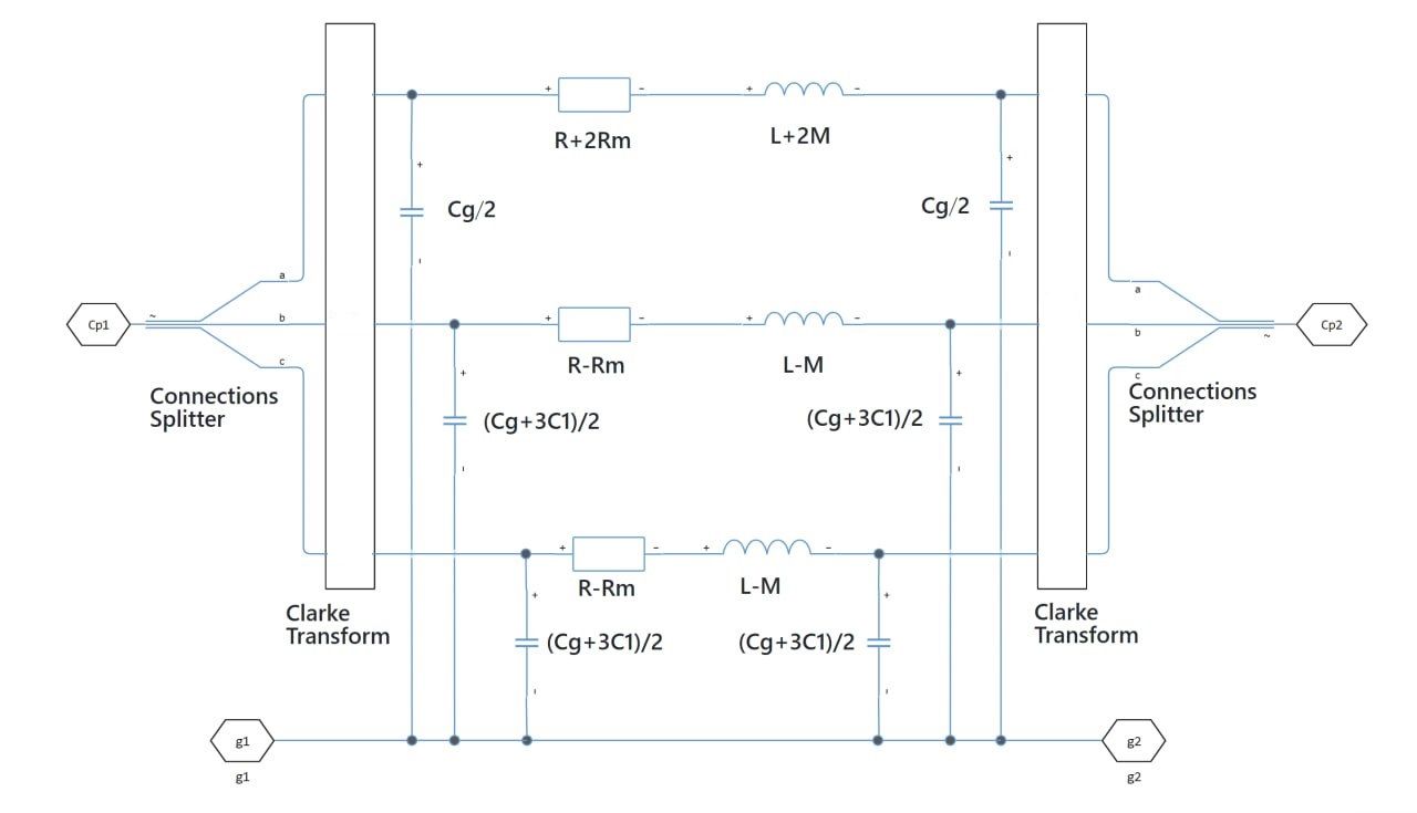
The figure shows an equivalent electrical circuit of one section of the line, constructed according to a U-shaped substitution scheme using the Clark transform.
To increase the accuracy, you can use the parameter Number of segments to repeat the U-shaped section N times, resulting in a transmission line model of N segments. A larger number of segments significantly slows down the modeling process.
Propagation speeds
Block Transmission Line (Three-Phase) calculates the propagation velocities of a direct sequence using the following equations:
-
— serial impedance;
-
— bandwidth;
-
— the distribution constant.
-
— the speed of propagation, where .
For the propagation velocity of the zero sequence, the equations are the same, but , , , , , and equal , , , , , and accordingly.
Ports
Conserving
#
~1
—
three-phase port
electricity
Details
Three-phase electrical port.
| Program usage name |
|
#
~2
—
three-phase port
electricity
Details
Three-phase electrical port.
| Program usage name |
|
#
g1
—
ground connection at the end ~1
electricity
Details
Electrical port, corresponds to the ground connection on the ~1 side.
| Program usage name |
|
#
g2
—
ground connection at the end ~2
electricity
Details
Electrical port, corresponds to the ground connection on the ~2 side.
| Program usage name |
|
Parameters
Main
#
Parameterization —
the method of setting line parameters
Balanced impedance | Sequence impedance | Sequence impedance (R, X, B)
Details
The line parameters are set in the following way:
-
Balanced impedance— set the same series active resistance, series inductance and transverse capacitance for all phases; -
Sequence impedance— set the active resistance, inductance and transverse capacitance ( , , ) for the forward and zero sequences; -
Sequence impedance (R, X, B)— set the active resistance, inductive resistance and capacitive conductivity ( , , ) for the forward and zero sequences.
The connection parameters between the lines are set in values , , zero sequence, if the option is selected Sequence impedance (R, X, B), and in magnitudes , , zero sequence otherwise.
| Values |
|
| Default value |
|
| Program usage name |
|
| Evaluatable |
No |
#
Line length —
length of the power transmission line
m | um | mm | cm | km | in | ft | yd | mi | nmi
Details
The length of the power transmission line.
| Units |
|
| Default value |
|
| Program usage name |
|
| Evaluatable |
Yes |
#
Frequency used for rlcg specification —
the frequency for which the RLC or RXB parameters are set
Hz | kHz | MHz | GHz
Details
At a given frequency, the transmission line parameters are adjusted to more accurately represent the resistances of the forward and zero sequences.
| Units |
|
| Default value |
|
| Program usage name |
|
| Evaluatable |
Yes |
#
Resistance —
line resistivity
Ohm/m | GOhm/m | MOhm/m | kOhm/m | mOhm/m | Ohm/km
Details
The resistance of the transmission line per phase per unit length.
Dependencies
To use this parameter, set for the parameter Parameterization meaning Balanced impedance.
| Units |
|
| Default value |
|
| Program usage name |
|
| Evaluatable |
Yes |
#
Inductance —
specific intrinsic inductance of the transmission line
H/m | mH/m | nH/m | uH/m | H/km | mH/km
Details
The intrinsic phase inductance of the transmission line per unit length.
Dependencies
To use this parameter, set for the parameter Parameterization meaning Balanced impedance.
| Units |
|
| Default value |
|
| Program usage name |
|
| Evaluatable |
Yes |
#
Mutual inductance —
specific mutual inductance
H/m | mH/m | nH/m | uH/m | H/km | mH/km
Details
Mutual phase inductance per unit length. Set this value to 0 to eliminate mutual inductance.
Dependencies
To use this parameter, set for the parameter Parameterization meaning Balanced impedance.
| Units |
|
| Default value |
|
| Program usage name |
|
| Evaluatable |
Yes |
#
Line-line capacitance —
specific capacity
mF/m | nF/m | pF/m | uF/m | F/km | uF/km
Details
Line capacity per unit length.
Dependencies
To use this parameter, set for the parameter Parameterization meaning Balanced impedance.
| Units |
|
| Default value |
|
| Program usage name |
|
| Evaluatable |
Yes |
#
Line-ground capacitance —
specific grounding capacity
mF/m | nF/m | pF/m | uF/m | F/km | uF/km
Details
Grounding capacity per unit length.
Dependencies
To use this parameter, set for the parameter Parameterization meaning Balanced impedance.
| Units |
|
| Default value |
|
| Program usage name |
|
| Evaluatable |
Yes |
#
Mutual resistance —
specific mutual resistance of phases
Ohm/m | GOhm/m | MOhm/m | kOhm/m | mOhm/m | Ohm/km
Details
The mutual resistance of the phases per unit length. The default value is 0.0 (there is no mutual resistance between the phases).
Dependencies
To use this parameter, set for the parameter Parameterization meaning Balanced impedance.
| Units |
|
| Default value |
|
| Program usage name |
|
| Evaluatable |
Yes |
#
Positive-sequence resistance —
active linear resistance of the forward sequence
Ohm/m | GOhm/m | MOhm/m | kOhm/m | mOhm/m | Ohm/km
Details
Active linear resistance of the forward sequence. This value must be greater than zero.
Dependencies
To use this parameter, set for the parameter Parameterization meaning Sequence impedance (R, X, B) or Sequence impedance.
| Units |
|
| Default value |
|
| Program usage name |
|
| Evaluatable |
Yes |
#
Zero-sequence resistance —
active linear resistance of the zero sequence
Ohm/m | GOhm/m | MOhm/m | kOhm/m | mOhm/m | Ohm/km
Details
Active linear resistance of the zero sequence. This value must be greater than zero.
Dependencies
To use this parameter, set for the parameter Parameterization meaning Sequence impedance (R, X, B) or Sequence impedance.
| Units |
|
| Default value |
|
| Program usage name |
|
| Evaluatable |
Yes |
#
Positive-sequence inductance —
specific inductance of the direct sequence
H/m | mH/m | nH/m | uH/m | H/km | mH/km
Details
The specific inductance of the direct sequence. This value must be greater than zero.
Dependencies
To use this parameter, set for the parameter Parameterization meaning Sequence impedance.
| Units |
|
| Default value |
|
| Program usage name |
|
| Evaluatable |
Yes |
#
Zero-sequence inductance —
specific inductance of the zero sequence
H/m | mH/m | nH/m | uH/m | H/km | mH/km
Details
The specific inductance of the zero sequence. This value must be greater than zero.
Dependencies
To use this parameter, set for the parameter Parameterization meaning Sequence impedance.
| Units |
|
| Default value |
|
| Program usage name |
|
| Evaluatable |
Yes |
#
Positive-sequence reactance —
linear inductive resistance of the direct sequence
Ohm/m | GOhm/m | MOhm/m | kOhm/m | mOhm/m | Ohm/km
Details
Linear inductive resistance of the direct sequence. This value must be greater than zero.
Dependencies
To use this parameter, set for the parameter Parameterization meaning Sequence impedance (R, X, B).
| Units |
|
| Default value |
|
| Program usage name |
|
| Evaluatable |
Yes |
#
Zero-sequence reactance —
linear inductive resistance of the zero sequence
Ohm/m | GOhm/m | MOhm/m | kOhm/m | mOhm/m | Ohm/km
Details
Linear inductive resistance of the zero sequence. This value must be greater than zero.
Dependencies
To use this parameter, set for the parameter Parameterization meaning Sequence impedance (R, X, B).
| Units |
|
| Default value |
|
| Program usage name |
|
| Evaluatable |
Yes |
#
Positive-sequence capacitance —
specific capacity of the direct sequence
mF/m | nF/m | pF/m | uF/m | F/km | uF/km
Details
The specific capacity of the direct sequence. This value must be greater than zero.
Dependencies
To use this parameter, set for the parameter Parameterization meaning Sequence impedance.
| Units |
|
| Default value |
|
| Program usage name |
|
| Evaluatable |
Yes |
#
Zero-sequence capacitance —
specific capacity of the zero sequence
mF/m | nF/m | pF/m | uF/m | F/km | uF/km
Details
The specific capacity of the zero sequence. This value must be greater than zero.
Dependencies
To use this parameter, set for the parameter Parameterization meaning Sequence impedance.
| Units |
|
| Default value |
|
| Program usage name |
|
| Evaluatable |
Yes |
#
Positive-sequence capacitive conductance —
specific capacitive conductivity of the direct sequence
S/m | pS/m | nS/m | uS/km | uS/m | mS/m
Details
The specific capacitive conductivity of the direct sequence. This value must be greater than or equal to zero.
Dependencies
To use this parameter, set for the parameter Parameterization meaning Sequence impedance (R, X, B).
| Units |
|
| Default value |
|
| Program usage name |
|
| Evaluatable |
Yes |
#
Zero-sequence capacitive conductance —
specific capacitive conductivity of the zero sequence
S/m | pS/m | nS/m | uS/km | uS/m | mS/m
Details
The specific capacitive conductivity of the zero sequence. This value must be greater than zero.
Dependencies
To use this parameter, set for the parameter Parameterization meaning Sequence impedance (R, X, B).
| Units |
|
| Default value |
|
| Program usage name |
|
| Evaluatable |
Yes |
# Number of segments — number of segments
Details
The number of U-shaped segments in the model.
| Default value |
|
| Program usage name |
|
| Evaluatable |
Yes |