Coupled Lines (Three-Phase)
Three-phase lines with magnetic coupling.
blockType: AcausalElectricPowerSystems.Passive.Lines.ThreePhaseCoupled
|
Path in the library: |

Description
Block Coupled Lines (Three-Phase) simulates three magnetically coupled lines. Each line is characterized by inductance, series ohmic resistance, and parallel conduction. In addition, there is mutual inductance and mutual resistance between each pair of lines.
Use this unit when the magnetic coupling in a three-phase network is not negligible. These effects are most noticeable when:
-
The lines are parallel and located close to each other.
-
The intrinsic inductance of the lines is high.
-
The frequency of alternating current in the network is high.
To simulate the capacitive coupling between the lines, use the block Transmission Line (Three-Phase).
The equivalent scheme
An equivalent diagram shows the relationship between two arbitrary phases. and . The block simulates a magnetic coupling using the following equivalent circuit between each pair of phases , and .
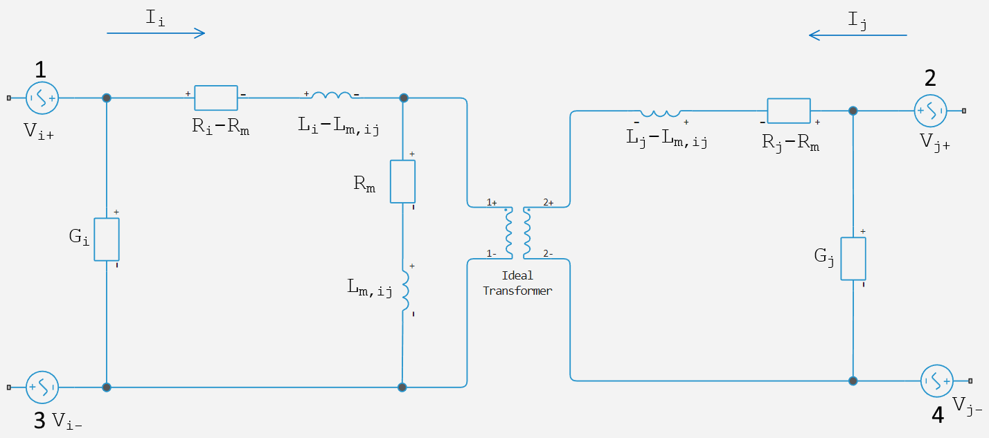
In this diagram:
-
and — ohmic resistances of the lines and ;
-
and — intrinsic line inductance and ;
-
— magnetic resistance between two lines. This parameter can be used to account for losses in the common neutral (see below);
-
— mutual inductance of the lines and ;
-
and — line leakage conductivity and ;
-
and — voltage drop on the lines and ;
-
and — currents through resistances - and - ;
The equations
The defining equation for this block is:
where
-
;
-
;
-
, and As a rule, they are not equal to the currents in the lines , and . The currents of the lines make up the following vector:
.
Inductive coupling
To quantify the magnetic coupling between two lines, you can use the coupling coefficient or the coupling coefficient. . The coupling coefficient relates the mutual inductance to the intrinsic inductance of the line:
This coefficient should be in the range of , where a negative value indicates a change in the orientation of one of the coils. The value of the value indicates that:
-
— there is no magnetic connection between the two lines.
-
— the two lines are weakly connected and the mutual magnetic effects are small.
-
— the two lines are strongly connected and the mutual magnetic effects are great.
Mutual resistance
If the three lines have a common neutral, the resistance of this return path can be modeled using the parameter Mutual resistance . This approach is equivalent to installing Mutual resistance equal to zero and an explicit indication of the neutral resistance as shown in the diagram below.
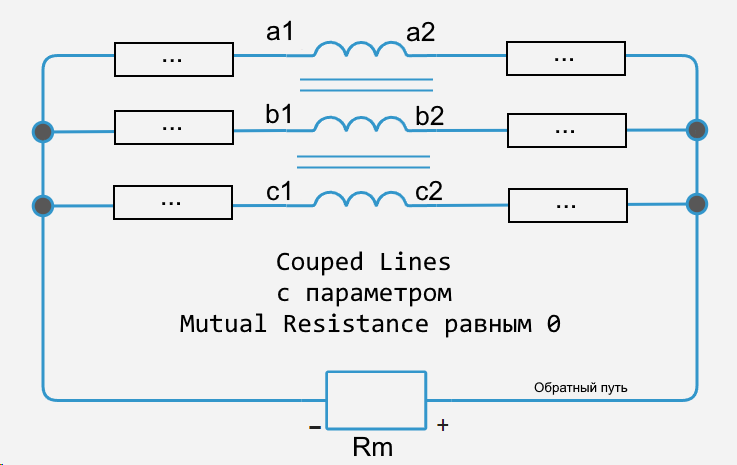
If the three lines do not have a common neutral, set the parameter Mutual resistance equal to zero and explicitly add each of the neutral resistances to the model.
Variables
Use the parameter group Initial Targets to set the priority and initial target values for the block parameter variables before modeling. For more information, see Configuring physical blocks using target values.
Ports
Conserving
#
~1
—
positive terminals
electricity
Details
Three-phase electrical port, corresponds to the positive terminals of the lines , and .
| Program usage name |
|
#
~2
—
negative terminals
electricity
Details
Three-phase electrical port, corresponds to the negative terminals of the lines , and .
| Program usage name |
|
Parameters
Main
#
Parameterization —
parameterization of line impedance
Balanced impedance | General impedance | Sequence impedance
Details
Specify how to parameterize the impedance of the three lines:
-
Balanced impedance— The same series resistance, series inductance and parallel leakage conductivity are used for all lines. -
General impedance— Series resistance, series inductance and parallel leakage conductivity are used separately for each line. -
Sequence impedance— A three-phase balanced inductive and resistive resistance is used with mutual coupling between the phases. This provides a more convenient way to enter system parameters in terms of direct and zero sequence resistances and inductors than intrinsic and reciprocal resistances and inductors.
| Values |
|
| Default value |
|
| Program usage name |
|
| Evaluatable |
No |
#
Line a inductance —
self-inductance of line A
H | nH | uH | mH
Details
Self-inductance of the line . This value must be greater than zero.
Dependencies
To use this parameter, set for Parameterization meaning General impedance.
| Units |
|
| Default value |
|
| Program usage name |
|
| Evaluatable |
Yes |
#
Line b inductance —
self-inductance of line B
H | nH | uH | mH
Details
Self-inductance of the line . This value must be greater than zero.
Dependencies
To use this parameter, set for Parameterization meaning General impedance.
| Units |
|
| Default value |
|
| Program usage name |
|
| Evaluatable |
Yes |
#
Line c inductance —
self-inductance of line C
H | nH | uH | mH
Details
Self-inductance of the line . This value must be greater than zero.
Dependencies
To use this parameter, set for Parameterization meaning General impedance.
| Units |
|
| Default value |
|
| Program usage name |
|
| Evaluatable |
Yes |
#
Line inductance —
line inductance
H | nH | uH | mH
Details
The intrinsic inductance of the lines , and . This value must be greater than zero.
Dependencies
To use this parameter, set for Parameterization meaning Balanced impedance.
| Units |
|
| Default value |
|
| Program usage name |
|
| Evaluatable |
Yes |
#
Line a-b mutual inductance —
mutual inductance between a and b
H | nH | uH | mH
Details
Mutual inductance between the lines and .
If you know the coupling coefficient, set this value to . In order to have a physically realizable mutual inductance, this value must satisfy:
Dependencies
To use this parameter, set for Parameterization meaning General impedance.
| Units |
|
| Default value |
|
| Program usage name |
|
| Evaluatable |
Yes |
#
Line a-c mutual inductance —
mutual inductance between lines A and C
H | nH | uH | mH
Details
Mutual inductance between the lines and .
If you know the coupling coefficient, set this value to . In order to have a physically realizable mutual inductance, this value must satisfy:
Dependencies
To use this parameter, set for Parameterization meaning General impedance.
| Units |
|
| Default value |
|
| Program usage name |
|
| Evaluatable |
Yes |
#
Line b-c mutual inductance —
mutual inductance between lines b and C
H | nH | uH | mH
Details
Mutual inductance between the lines and .
If you know the coupling coefficient, set this value to . In order to have a physically realizable mutual inductance, this value must satisfy:
Dependencies
To use this parameter, set for Parameterization meaning General impedance.
| Units |
|
| Default value |
|
| Program usage name |
|
| Evaluatable |
Yes |
#
Mutual inductance —
mutual inductance
H | nH | uH | mH
Details
Mutual inductance of each pair of lines. If you know the coupling coefficient, set this value to , where — the intrinsic inductance of each of the lines. To be physically realizable, this value must satisfy the inequality:
Dependencies
To use this parameter, set for Parameterization meaning Balanced impedance.
| Units |
|
| Default value |
|
| Program usage name |
|
| Evaluatable |
Yes |
#
Positive-sequence inductance —
forward sequence inductance
H | nH | uH | mH
Details
The inductance of the direct sequence.
Dependencies
To use this parameter, set for Parameterization meaning Sequence impedance.
| Units |
|
| Default value |
|
| Program usage name |
|
| Evaluatable |
Yes |
#
Zero-sequence inductance —
zero-sequence inductance
H | nH | uH | mH
Details
The inductance of the zero sequence.
Dependencies
To use this parameter, set for Parameterization meaning Sequence impedance.
| Units |
|
| Default value |
|
| Program usage name |
|
| Evaluatable |
Yes |
Resistance
#
Line a resistance —
serial resistance of line A
Ohm | mOhm | kOhm | MOhm | GOhm
Details
Consistent line resistance . This value must be greater than or equal to zero.
Dependencies
To use this parameter, set for Parameterization meaning General impedance.
| Units |
|
| Default value |
|
| Program usage name |
|
| Evaluatable |
Yes |
#
Line b resistance —
serial resistance of line B
Ohm | mOhm | kOhm | MOhm | GOhm
Details
Consistent line resistance . This value must be greater than or equal to zero.
Dependencies
To use this parameter, set for Parameterization meaning General impedance.
| Units |
|
| Default value |
|
| Program usage name |
|
| Evaluatable |
Yes |
#
Line c resistance —
serial resistance of line C
Ohm | mOhm | kOhm | MOhm | GOhm
Details
Consistent line resistance . This value must be greater than or equal to zero.
Dependencies
To use this parameter, set for Parameterization meaning General impedance.
| Units |
|
| Default value |
|
| Program usage name |
|
| Evaluatable |
Yes |
#
Line resistance —
consistent resistance
Ohm | mOhm | kOhm | MOhm | GOhm
Details
Consistent line resistance , and . This value must be greater than or equal to zero.
Dependencies
To use this parameter, set for Parameterization meaning Balanced impedance.
| Units |
|
| Default value |
|
| Program usage name |
|
| Evaluatable |
Yes |
#
Mutual resistance —
mutual resistance
Ohm | mOhm | kOhm | MOhm | GOhm
Details
The mutual resistance of each pair of lines. This value must be greater than or equal to zero.
Use this value to account for losses in the common neutral.
Dependencies
To use this parameter, set for Parameterization meaning Balanced impedance.
| Units |
|
| Default value |
|
| Program usage name |
|
| Evaluatable |
Yes |
#
Line a leakage conductance —
Parallel leakage line A
S | nS | uS | mS | 1/Ohm
Details
Parallel leakage line conductivity . This value must be greater than or equal to zero.
Dependencies
To use this parameter, set for Parameterization meaning General impedance.
| Units |
|
| Default value |
|
| Program usage name |
|
| Evaluatable |
Yes |
#
Line b leakage conductance —
parallel leakage line B conductivity
S | nS | uS | mS | 1/Ohm
Details
Parallel leakage line conductivity . This value must be greater than or equal to zero.
Dependencies
To use this parameter, set for Parameterization meaning General impedance.
| Units |
|
| Default value |
|
| Program usage name |
|
| Evaluatable |
Yes |
#
Line c leakage conductance —
parallel leakage line C conductivity
S | nS | uS | mS | 1/Ohm
Details
Parallel leakage line conductivity . This value must be greater than or equal to zero.
Dependencies
To use this parameter, set for Parameterization meaning General impedance.
| Units |
|
| Default value |
|
| Program usage name |
|
| Evaluatable |
Yes |
#
Positive-sequence resistance —
sequential resistance of direct sequence
Ohm | mOhm | kOhm | MOhm | GOhm
Details
Sequential resistance to direct sequence.
Dependencies
To use this parameter, set for Parameterization meaning Sequence impedance.
| Units |
|
| Default value |
|
| Program usage name |
|
| Evaluatable |
Yes |
#
Zero-sequence resistance —
sequential resistance of the zero sequence
Ohm | mOhm | kOhm | MOhm | GOhm
Details
The sequential resistance of the zero sequence.
Dependencies
To use this parameter, set for Parameterization meaning Sequence impedance.
| Units |
|
| Default value |
|
| Program usage name |
|
| Evaluatable |
Yes |
#
Line leakage conductance —
parallel leakage conductivity
S | nS | uS | mS | 1/Ohm
Details
Parallel line leakage conductivity , and . This value must be greater than or equal to zero.
Dependencies
To use this parameter, set for Parameterization meaning Balanced impedance.
| Units |
|
| Default value |
|
| Program usage name |
|
| Evaluatable |
Yes |