Demodulator (CE)
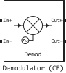
The RF demodulator model.
blockType: SubSystem
|
Path in the library: |
Ports
Conserving
#
In+
—
RF input signal
electricity
Details
A positive electrical port connected to the RF input signal.
| Program usage name |
|
#
In−
—
RF input signal
electricity
Details
A negative electrical port connected to the RF input signal.
| Program usage name |
|
#
Out+
—
The output signal
electricity
Details
A positive electrical port connected to the output signal.
| Program usage name |
|
#
Out−
—
The output signal
electricity
Details
The negative electrical port connected to the output signal.
| Program usage name |
|
Parameters
IR Filter
IR Filter
# Passband frequency, Hz — bandwidth frequency for low-pass filters
Details
The bandwidth frequency for low-pass filters, set as a scalar in Hz.
Dependencies
To use this parameter, set for the parameter Design method meaning Butterworth or Chebyshev and for the parameter Filter type meaning Lowpass.
| Default value |
|
| Program usage name |
|
| Tunable |
No |
| Evaluatable |
Yes |
# Passband frequency, Hz — bandwidth frequency for high-pass filters
Details
The bandwidth frequency for high-pass filters, set as a scalar in Hz.
Dependencies
To use this parameter, set for the parameter Design method meaning Butterworth or Chebyshev and for the parameter Filter type meaning Highpass.
| Default value |
|
| Program usage name |
|
| Tunable |
No |
| Evaluatable |
Yes |
# Passband frequencies, Hz — bandwidth frequencies for bandpass filters
Details
The bandwidth frequencies for bandpass filters, specified as a vector of a pair of numbers in Hz. This option is not available for notch filters.
Dependencies
To use this parameter, set for the parameter Design method meaning Butterworth or Chebyshev and for the parameter Filter type meaning Bandpass.
| Default value |
|
| Program usage name |
|
| Tunable |
No |
| Evaluatable |
Yes |
# Stopband frequencies, Hz — delay band frequencies for bandpass filters
Details
The delay band frequencies for bandpass filters, specified as a vector of a pair of numbers in Hz This option is not available for bandpass filters.
Dependencies
To use this parameter, set for the parameter Design method meaning Butterworth or Chebyshev and for the parameter Filter type meaning Bandstop.
| Default value |
|
| Program usage name |
|
| Tunable |
No |
| Evaluatable |
Yes |
#
Design method —
type of simulation
Butterworth | Chebyshev
Details
The type of simulation. The block models Butterworth filter or Chebyshev filter of the type specified in the parameter Filter type, and the model specified in the parameter Implementation.
Dependencies
To use this option, check the box Add Image Reject filter.
| Values |
|
| Default value |
|
| Program usage name |
|
| Tunable |
No |
| Evaluatable |
Yes |
#
Filter type —
filter type
Lowpass | Highpass | Bandpass | Bandstop
Details
The type of filter. The block simulates a low-pass filter, an upper-pass filter, a bandpass filter, or a notch filter, the type of which is specified in the parameter Design method.
Dependencies
To use this option, check the box Add Image Reject filter.
| Values |
|
| Default value |
|
| Program usage name |
|
| Tunable |
No |
| Evaluatable |
Yes |
#
Implementation —
realization
LC Tee | LC Pi
Details
An implementation defined by one of the following values:
-
LC Tee— simulation of an analog filter with an LC Tee-type structure with concentrated parameters, if for the parameter Design method the value is setButterworthorChebyshev. -
LC Pi— simulation of an analog filter with an LC structure of type Pi with concentrated parameters, if for the parameter Design method the value is setButterworthorChebyshev.
| Values |
|
| Default value |
|
| Program usage name |
|
| Tunable |
No |
| Evaluatable |
Yes |
# Filter order — filter order
Details
The filter order, set as a scalar. If for the parameter Filter type the value is set Lowpass or Highpass, then the filter order is determined by the number of concentrated memory elements. If for the parameter Filter type the value is set Bandpass or Bandstop, the number of concentrated memory elements is twice the filter order.
|
For Chebyshev filters of even order, the resistance ratio is to implement the Tee network and to implement the Pi network: where — ripple in the bandwidth in dB. |
Dependencies
To use this parameter,
set for the parameter Design method meaning Butterworth or Chebyshev.
| Default value |
|
| Program usage name |
|
| Tunable |
No |
| Evaluatable |
Yes |
# Passband attenuation, dB — bandwidth attenuation
Details
Bandwidth attenuation, specified as a scalar in dB. For bandpass filters, this value is applied equally to both edges of the bandwidth.
Dependencies
To use this parameter, set for the parameter Design method meaning Butterworth or Chebyshev and for the parameter Filter type meaning Lowpass, Highpass or Bandpass.
| Default value |
|
| Program usage name |
|
| Tunable |
No |
| Evaluatable |
Yes |
# Stopband attenuation, dB — attenuation in the delay band
Details
The attenuation in the delay band, set as a scalar in dB. For notch filters, this value is applied equally to both edges of the delay band.
Dependencies
To use this parameter, set for the parameter Design method meaning Butterworth or Chebyshev and for the parameter Filter type meaning Bandstop.
| Default value |
|
| Program usage name |
|
| Tunable |
No |
| Evaluatable |
Yes |
# Source impedance, Ohm — input impedance of the source
Details
The input impedance of the source, set as a scalar in ohms.
Dependencies
To use this parameter, set for the parameter Design method meaning Butterworth or Chebyshev.
| Default value |
|
| Program usage name |
|
| Tunable |
No |
| Evaluatable |
Yes |
# Load impedance, Ohm — load output impedance
Details
The output impedance of the load, set as a scalar in ohms.
Dependencies
To use this parameter, set for the parameter Design method meaning Butterworth or Chebyshev.
| Default value |
|
| Program usage name |
|
| Tunable |
No |
| Evaluatable |
Yes |
CS Filter
CS Filter
# Passband frequency, Hz — bandwidth frequency for low-pass filters
Details
The bandwidth frequency for low-pass filters, set as a scalar in Hz.
Dependencies
To use this parameter, set for the parameter Design method meaning Butterworth or Chebyshev and for the parameter Filter type meaning Lowpass.
| Default value |
|
| Program usage name |
|
| Tunable |
No |
| Evaluatable |
Yes |
# Passband frequency, Hz — bandwidth frequency for high-pass filters
Details
The bandwidth frequency for high-pass filters, set as a scalar in Hz.
Dependencies
To use this parameter, set for the parameter Design method meaning Butterworth or Chebyshev and for the parameter Filter type meaning Highpass.
| Default value |
|
| Program usage name |
|
| Tunable |
No |
| Evaluatable |
Yes |
# Passband frequencies, Hz — bandwidth frequencies for bandpass filters
Details
The bandwidth frequencies for bandpass filters, specified as a vector of a pair of numbers in Hz. This option is not available for notch filters.
Dependencies
To use this parameter, set for the parameter Design method meaning Butterworth or Chebyshev and for the parameter Filter type meaning Bandpass.
| Default value |
|
| Program usage name |
|
| Tunable |
No |
| Evaluatable |
Yes |
# Stopband frequencies, Hz — delay band frequencies for bandpass filters
Details
The delay band frequencies for bandpass filters, specified as a vector of a pair of numbers in Hz This option is not available for bandpass filters.
Dependencies
To use this parameter, set for the parameter Design method meaning Butterworth or Chebyshev and for the parameter Filter type meaning Bandstop.
| Default value |
|
| Program usage name |
|
| Tunable |
No |
| Evaluatable |
Yes |
#
Design method —
type of simulation
Butterworth | Chebyshev
Details
The type of simulation. The block models Butterworth filter or Chebyshev filter of the type specified in the parameter Filter type, and the model specified in the parameter Implementation.
Dependencies
To use this option, check the box Add Channel Select filter.
| Values |
|
| Default value |
|
| Program usage name |
|
| Tunable |
No |
| Evaluatable |
Yes |
#
Filter type —
filter type
Lowpass | Highpass | Bandpass | Bandstop
Details
The type of filter. The block simulates a low-pass filter, an upper-pass filter, a bandpass filter, or a notch filter, the type of which is specified in the parameter Design method.
Dependencies
To use this option, check the box Add Channel Select filter.
| Values |
|
| Default value |
|
| Program usage name |
|
| Tunable |
No |
| Evaluatable |
Yes |
#
Implementation —
realization
LC Tee | LC Pi
Details
An implementation defined by one of the following values:
-
LC Tee— simulation of an analog filter with an LC Tee-type structure with concentrated parameters, if for the parameter Design method the value is setButterworthorChebyshev. -
LC Pi— simulation of an analog filter with an LC structure of type Pi with concentrated parameters, if for the parameter Design method the value is setButterworthorChebyshev.
| Values |
|
| Default value |
|
| Program usage name |
|
| Tunable |
No |
| Evaluatable |
Yes |
# Filter order — filter order
Details
The filter order, set as a scalar. If for the parameter Filter type the value is set Lowpass or Highpass, then the filter order is determined by the number of concentrated memory elements. If for the parameter Filter type the value is set Bandpass or Bandstop, the number of concentrated memory elements is twice the filter order.
|
For Chebyshev filters of even order, the resistance ratio is to implement the Tee network and to implement the Pi network: where — ripple in the bandwidth in dB. |
Dependencies
To use this parameter,
set for the parameter Design method meaning Butterworth or Chebyshev.
| Default value |
|
| Program usage name |
|
| Tunable |
No |
| Evaluatable |
Yes |
# Passband attenuation, dB — bandwidth attenuation
Details
Bandwidth attenuation, specified as a scalar in dB. For bandpass filters, this value is applied equally to both edges of the bandwidth.
Dependencies
To use this parameter, set for the parameter Design method meaning Butterworth or Chebyshev and for the parameter Filter type meaning Lowpass, Highpass or Bandpass.
| Default value |
|
| Program usage name |
|
| Tunable |
No |
| Evaluatable |
Yes |
# Stopband attenuation, dB — attenuation in the delay band
Details
The attenuation in the delay band, set as a scalar in dB. For notch filters, this value is applied equally to both edges of the delay band.
Dependencies
To use this parameter, set for the parameter Design method meaning Butterworth or Chebyshev and for the parameter Filter type meaning Bandstop.
| Default value |
|
| Program usage name |
|
| Tunable |
No |
| Evaluatable |
Yes |
# Source impedance, Ohm — input impedance of the source
Details
The input impedance of the source, set as a scalar in ohms.
Dependencies
To use this parameter, set for the parameter Design method meaning Butterworth or Chebyshev.
| Default value |
|
| Program usage name |
|
| Tunable |
No |
| Evaluatable |
Yes |
# Load impedance, Ohm — load output impedance
Details
The output impedance of the load, set as a scalar in ohms.
Dependencies
To use this parameter, set for the parameter Design method meaning Butterworth or Chebyshev.
| Default value |
|
| Program usage name |
|
| Tunable |
No |
| Evaluatable |
Yes |
Main
Main
#
Source of conversion gain —
parameter of the conversion gain source
Available power gain
Details
The parameter of the conversion gain source, set as Available power gain — relates the ratio of the output power of one sideband to the input power. This calculation assumes a consistent load and a terminal load of the source.
| Values |
|
| Default value |
|
| Program usage name |
|
| Tunable |
No |
| Evaluatable |
Yes |
# Available power gain, dB — The ratio of the output power to the input power
Details
The ratio of the output power to the input power, given as a scalar in dB.
Dependencies
To use this parameter, set for the parameter Source of conversion gain meaning Available power gain.
| Default value |
|
| Program usage name |
|
| Tunable |
No |
| Evaluatable |
Yes |
# Local oscillator frequency, Hz — The frequency of the heterodyne
Details
The frequency of the heterodyne, set as a scalar in Hz.
| Default value |
|
| Program usage name |
|
| Tunable |
No |
| Evaluatable |
Yes |
# Input impedance, Ohm — input impedance of the demodulator
Details
The input impedance of the demodulator, set as a scalar in ohms.
| Default value |
|
| Program usage name |
|
| Tunable |
No |
| Evaluatable |
Yes |
# Output impedance, Ohm — output impedance of the demodulator
Details
The output impedance of the demodulator, set as a scalar in ohms.
| Default value |
|
| Program usage name |
|
| Tunable |
No |
| Evaluatable |
Yes |
Filters
# Add Image Reject filter — image rejection filter parameters
Details
Check this box to add a tab. IR Filter with the parameters of the image rejection filter (Image Reject, IR). Uncheck this box to delete the tab.
| Default value |
|
| Program usage name |
|
| Tunable |
No |
| Evaluatable |
Yes |
# Add Channel Select filter — channel selection filter parameters
Details
Check this box to add a tab. CS Filter with the parameters of the channel selection filter (Channel Select, CS). Uncheck this box to delete the tab.
| Default value |
|
| Program usage name |
|
| Tunable |
No |
| Evaluatable |
Yes |
Impairments
Impairments
# LO to In isolation, dB — the ratio of the amplitude of the voltage of the heterodyne to the leakage voltage at the input port
Details
The ratio of the amplitude of the voltage of the heterodyne to the leakage voltage at the input port (RF), given as a scalar in dB.
| Default value |
|
| Program usage name |
|
| Tunable |
No |
| Evaluatable |
Yes |