GP-ID-34 pin assignment
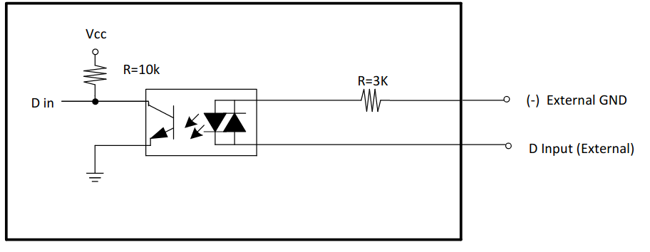
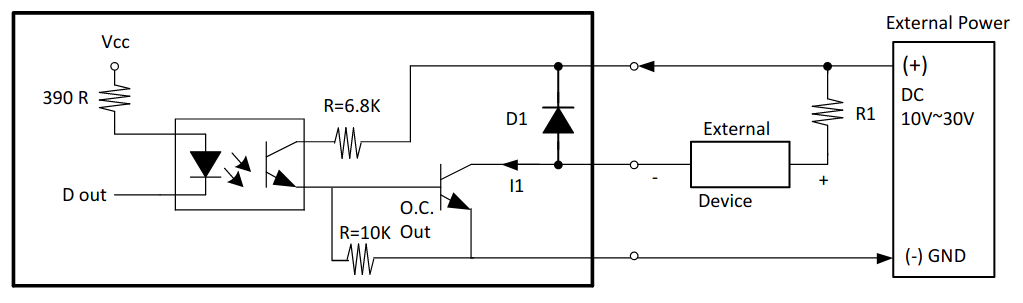
Digital inputs and digital outputs
Pin assignment on the first terminal module supplied for module configuration with 16 digital inputs and 16 digital outputs:
| Contact | Port | Signal | Contact | Port | Signal |
|---|---|---|---|---|---|
1 |
- |
EXT.GND |
21 |
E |
DO1 |
2 |
A |
DI1 |
22 |
E |
DO2 |
3 |
A |
DI2 |
23 |
E |
DO3 |
4 |
A |
DI3 |
24 |
E |
DO4 |
5 |
A |
DI4 |
25 |
E |
DO5 |
6 |
A |
DI5 |
26 |
E |
DO6 |
7 |
A |
DI6 |
27 |
E |
DO7 |
8 |
A |
DI7 |
28 |
E |
DO8 |
9 |
A |
DI8 |
29 |
F |
DO1 |
10 |
B |
DI1 |
30 |
F |
DO2 |
11 |
B |
DI2 |
31 |
F |
DO3 |
12 |
B |
DI3 |
32 |
F |
DO4 |
13 |
B |
DI4 |
33 |
F |
DO5 |
14 |
B |
DI5 |
34 |
F |
DO6 |
15 |
B |
DI6 |
35 |
F |
DO7 |
16 |
B |
DI7 |
36 |
F |
DO8 |
17 |
B |
DI8 |
37 |
- |
EXT.PWR |
18 |
- |
INT.GND |
- |
- |
- |
19 |
- |
N/A |
- |
- |
- |
20 |
- |
EXT.GND |
- |
- |
- |
Pin assignment on the second terminal module supplied for module configuration with 32 digital inputs and 32 digital outputs:
| Contact | Port | Signal | Contact | Port | Signal |
|---|---|---|---|---|---|
1 |
- |
EXT.GND |
21 |
G |
DO1 |
2 |
C |
DI1 |
22 |
G |
DO2 |
3 |
C |
DI2 |
23 |
G |
DO3 |
4 |
C |
DI3 |
24 |
G |
DO4 |
5 |
C |
DI4 |
25 |
G |
DO5 |
6 |
C |
DI5 |
26 |
G |
DO6 |
7 |
C |
DI6 |
27 |
G |
DO7 |
8 |
C |
DI7 |
28 |
G |
DO8 |
9 |
C |
DI8 |
29 |
H |
DO1 |
10 |
D |
DI1 |
30 |
H |
DO2 |
11 |
D |
DI2 |
31 |
H |
DO3 |
12 |
D |
DI3 |
32 |
H |
DO4 |
13 |
D |
DI4 |
33 |
H |
DO5 |
14 |
D |
DI5 |
34 |
H |
DO6 |
15 |
D |
DI6 |
35 |
H |
DO7 |
16 |
D |
DI7 |
36 |
H |
DO8 |
17 |
D |
DI8 |
37 |
- |
EXT.PWR |
18 |
- |
INT.GND |
- |
- |
- |
19 |
- |
N/A |
- |
- |
- |
20 |
- |
EXT.GND |
- |
- |
- |
Designations:
| DI1..DI8 |
Digital inputs 1 to 8 on the specified port. |
| DO1..DO8 |
Digital outputs 1 to 8 on the specified port.
|
| ETX.GND |
External power supply ground. |
| ETX.PWR |
Plus of the external power supply. |
| To operate the module, it is necessary to connect the external power supply. To do this, connect the GND and INT.GND ports to the external power supply ground, and apply a voltage of 9…24 V to the EXT.PWR pin. |