Purpose of GP-LC-45 pins
Analogue inputs and outputs
Pin assignment on the supplied terminal module:
Contact |
Signal |
Contact |
Signal |
|---|---|---|---|
1 |
X16 |
20 |
Y16 |
2 |
X15 |
21 |
Y15 |
3 |
X14 |
22 |
Y14 |
4 |
X13 |
23 |
Y13 |
5 |
X12 |
24 |
Y12 |
6 |
X11 |
25 |
Y11 |
7 |
X10 |
26 |
Y10 |
8 |
X9 |
27 |
Y9 |
9 |
X8 |
28 |
Y8 |
10 |
X7 |
29 |
Y7 |
11 |
X6 |
30 |
Y6 |
12 |
X5 |
31 |
Y5 |
13 |
X4 |
32 |
Y4 |
14 |
X3 |
33 |
Y3 |
15 |
X2 |
34 |
Y2 |
16 |
X1 |
35 |
Y1 |
17 |
AGND |
36 |
GND32 |
18 |
DAC1 |
37 |
NC |
19 |
DAC2 |
- |
- |
Designations:
| X1..X16 |
Non-inverting voltage input of channels 1…16 for differential mode. Channels 1…16 for common ground mode.
|
| DAC1, DAC2 |
DAC channel 1 and 2 outputs. |
| AGND |
Analogue ground. |
| GND32 |
In common ground mode: common inverting input of channels 1..32. For all modes must be connected to AGND (in differential mode - to increase noise immunity).
|
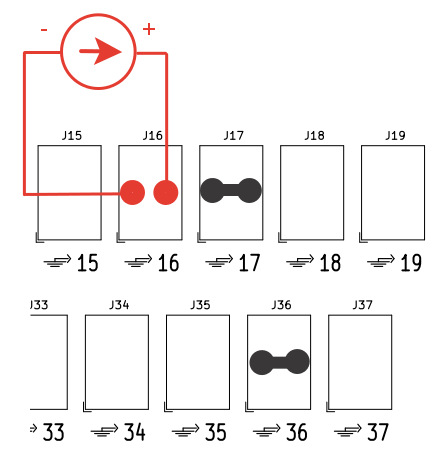
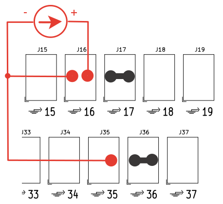
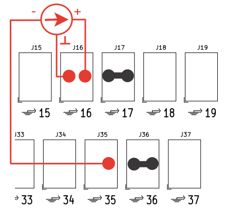
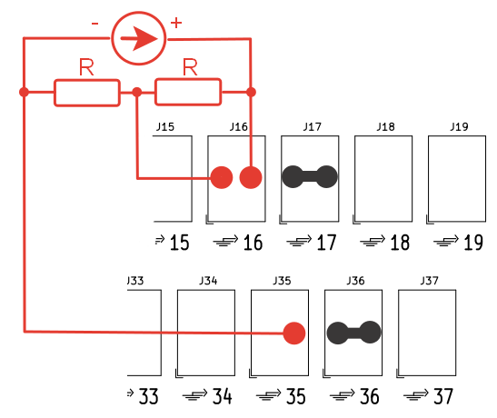
In case of completion with terminal module GP-RT-Terminal-37 for correct ADC operation it is necessary to install two jumper wires between pins 17, 36 and ground of the terminal module. An example of connection is shown in the figure:
The following are the basic options for connecting external signal sources using channel 1 as an example.
Connection of a single-phase source in the "common ground" mode.
Connection of a single-phase source in differential mode.
Connection of a differential source in the presence of an earth lead.
Connection of the differential source when there is no earth connection.
Digital inputs and outputs
Pin assignment on the supplied terminal module:
Contact |
Signal |
Contact |
Signal |
|---|---|---|---|
1 |
DGND |
20 |
DGND |
2 |
+3.3V |
21 |
+3.3V |
3 |
DO15 |
22 |
DO16 |
4 |
DO13 |
23 |
DO14 |
5 |
DO11 |
24 |
DO12 |
6 |
DO9 |
25 |
DO10 |
7 |
DO7 |
26 |
DO8 |
8 |
DO5 |
27 |
DO6 |
9 |
DO3 |
28 |
DO4 |
10 |
DO1 |
29 |
DO2 |
11 |
DI15 |
30 |
DI16 |
12 |
DI13 |
31 |
DI14 |
13 |
DI11 |
32 |
DI12 |
14 |
DI9 |
33 |
DI10 |
15 |
DI7 |
34 |
DI8 |
16 |
DI5 |
35 |
DI6 |
17 |
DI3 |
36 |
DI4 |
18 |
DI1 |
37 |
DI2 |
19 |
NC |
- |
- |
Designations:
| DI1..DI16 |
Digital inputs 1 to 16.
|
| NC |
Not used. |