Designation of MI-EL-45 pins
External connectors
There are two DB9F external connectors on the module. The pins are numbered as follows:
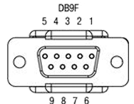
The upper DB9F connector is labelled X2 in the table and diagram, and the lower DB9F connector is labelled X3.
Pin assignment
| Connector | Contact | Circuit name | Connector | Contact | Circuit name |
|---|---|---|---|---|---|
X2 |
1 |
K1A_0 |
X3 |
1 |
K2A_0 |
X2 |
2 |
K1A_1 |
X3 |
2 |
K2A_1 |
X2 |
3 |
K1B_0 |
X3 |
3 |
K2B_0 |
X2 |
4 |
K1B_1 |
X3 |
4 |
K2B_1 |
X2 |
5 |
GND |
X3 |
5 |
GND |
X2 |
6 |
K3A_0 |
X3 |
6 |
K4A_0 |
X2 |
7 |
K3A_1 |
X3 |
7 |
K4A_1 |
X2 |
8 |
K3B_0 |
X3 |
8 |
K4B_0 |
X2 |
9 |
K3B_1 |
X3 |
9 |
K4B_1 |
- Designations in the circuit name
-
K(channel number: 1 to 4)(line number in channel: A or B)_(line polarity: 0 or 1)
Test wiring harness
The supplied test wiring harness provides direct connection of all four channels to the A and B lines. In this case, channels 1 and 3 are connected via one DB9M connector, and channels 2 and 4 are connected via another DB9M connector. Output from the test harness to an oscilloscope is also provided.
Connection type
By default, the board’s jumpers are set to direct connection. To connect via a matching transformer, the board jumpers need to be re-set.
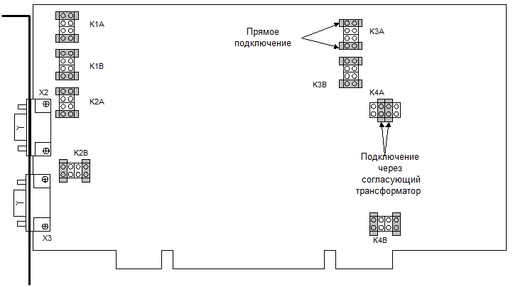
| Contacts closed | Connection to connector |
|---|---|
KXX 1-2 |
Direct connection. Positive contact. |
KXX 3-4 |
With matching transformer. Positive contact. |
KXX 5-6 |
With matching transformer. Negative contact. |
KXX 7-8 |
Direct connection. Negative contact. |
Designation of MI-EL-55 pins
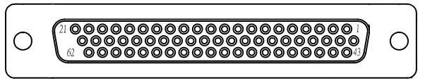
A DHR-44F connector is installed on the module. The pins are numbered as follows:
| Contact number | Output assignment |
|---|---|
3 |
K1AD1 |
19 |
K1AT1 |
18 |
K1AT0 |
2 |
K1AD0 |
1 |
K1BD1 |
17 |
K1BT1 |
31 |
K1BT0 |
16 |
K1BD0 |
7 |
K2AD1 |
23 |
K2AT1 |
22 |
K2AT0 |
6 |
K2AD0 |
5 |
K2BD1 |
21 |
K2BT1 |
20 |
K2BT0 |
4 |
K2BD0 |
11 |
K3AD1 |
27 |
K3AT1 |
26 |
K3AT0 |
10 |
K3AD0 |
9 |
K3BD1 |
25 |
K3BT1 |
24 |
K3BT0 |
8 |
K3BD0 |
15 |
K4AD1 |
44 |
K4AT1 |
30 |
K4AT0 |
14 |
K4AD0 |
13 |
K4BD1 |
29 |
K4BT1 |
28 |
K4BT0 |
12 |
K4BD0 |
Explanation of designations:
| K |
Channel number - 1,2,3,4
|
| Line polarity |
1 - positive contact; 0 - negative contact |
Test harness
The supplied test harness provides direct connection of all four channels to the A and B lines. Output from the test harness to an oscilloscope is provided.