Stages of building a physical model
Let’s consider building a physical model using the example of an RC circuit. An RC circuit consists of a resistor and a capacitor. Such circuits are often used for signal filtering, pulse generation, timers, and other tasks.
Selecting and configuring ad blocks
We will use the library blocks to build the model. Physical Modeling from the section Fundamental Components/Electrical:
| Subsection name and block name | The block icon | The object of the simulation |
|---|---|---|
Sources: DC Voltage Source |
|
An ideal voltage source. |
Elements: Resistor |
|
The resistor. |
Elements: Capacitor |
|
The capacitor. |
Elements: Electrical Reference |
|
Grounding. |
Sensors: Current Sensor |
|
An ammeter. |
Sensors: Voltage Sensor |
|
A voltmeter. |


You can find the block you need by searching in the library or entering its name in the search field that appears when you double-click on the canvas.
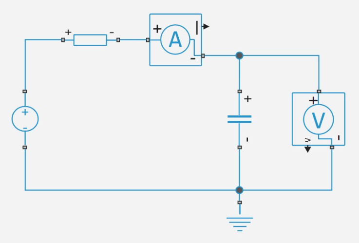
To add a block to the model, drag it with the mouse from the block library. ![]() Place them on the canvas in the correct order and connect them as they are connected in a real electrical circuit.:
Place them on the canvas in the correct order and connect them as they are connected in a real electrical circuit.:
Immediately after adding the blocks, they have default values. To change the settings, double-click on the block or right-click and select Options:
-
Constant voltage source DC Voltage Source: parameter Constant voltage =
5 In. -
The resistor Resistor: parameter Resistance =
100,000 Ohms. -
The capacitor Capacitor: parameter Capacity =
0.00001 F.
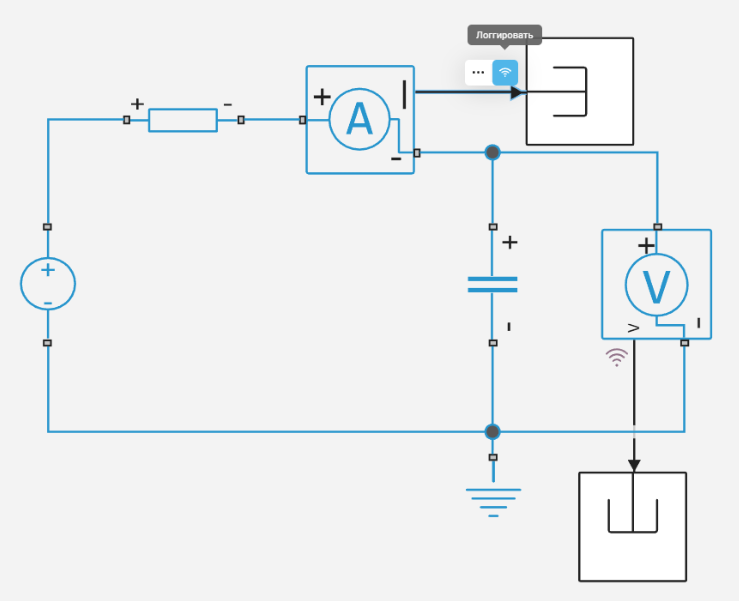
Ammeter Current Sensor outputs current to port I, voltmeter Voltage Sensor — the voltage in the port is V. These signals can be connected to Terminator from the library Basic/Receivers and enable recording.
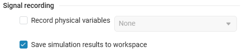
Signal Recording  allows you to save all the simulation results to a variable allows you to save all the simulation results to a variable simout. It collects only those signals for which recording is enabled. This variable allows you to save the simulation results to a CSV file in the future (for more information, see the article Software processing of simulation results in Engee).
|
|
The default variable is
|
For more information about building models in Engee, see Building a model.
Choosing a solver
Before the simulation, you need to choose a solver suitable for physical models. Usually, implicit solvers are used: Rosenbrock23, Rodas4, RadauIIA5, QNDF, ImplicitEuler, Trapezoid, TRBDF2, KenCarp4. They require fewer steps than explicit ones.
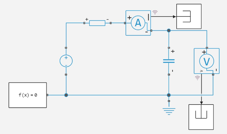
A physical model can include multiple networks. Each network (linked block diagram) requires one block Solver Configuration, which sets the parameters of the solver.
In this example, the parameters of the Solver Configuration block can be left by default.
After selecting the solver, all that remains is to select the simulation time and run the simulation.
Simulation results
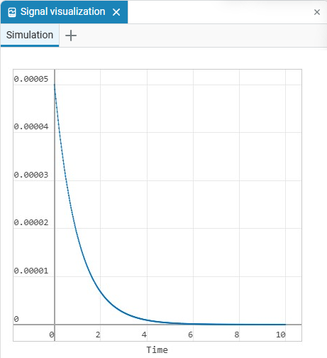
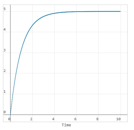
Let’s see the results in the window signal visualization ![]() . The graphs show how when charging a capacitor, the current decreases exponentially, and the voltage across it increases.
. The graphs show how when charging a capacitor, the current decreases exponentially, and the voltage across it increases.
Approaches to modeling physical objects
There are several ways to create a physical model in Engee, and the choice depends on your task and the required implementation.
The easiest and most effective way is to use ready-made blocks from the library. physical modeling. This is a classic approach: use the necessary physical blocks (like the resistor and capacitor in the example above) and connect them into a physical model. All the necessary equations are already embedded inside these blocks and do not require debugging.
If a suitable block is not available in the physical library, then you can describe its behavior yourself by creating your own physical component using Engee physical modeling language. The language allows you to describe an arbitrary physical model (physical variables, equations, laws, and relationships), and Engee figures out how to calculate it itself.
To visually see the difference between the approaches, study the demo model.: DC motor. In it, the same system is implemented in two ways: using ready-made blocks. Engee libraries and through a physical component created in a physical modeling language. When comparing the simulation results, it can be seen that both approaches produce identical results, which confirms the validity of using a physical component on a par with the physical blocks of the Engee library. At the same time, the component code is easy to read due to the simple syntax, and in some tasks this approach may be more convenient than classical modeling through physical blocks.
Thus, the Engee physical modeling language is not just a tool for creating individual components, but also a powerful tool for describing complex physical systems. At the same time, the code remains readable, which is extremely important when working with complex models.