Hierarchy of the model
Several blocks can be combined into a subsystem. This is necessary in cases where the number of blocks in the model is so large that it becomes inconvenient to work with them.
Creating a subsystem
There are several ways to combine blocks into a subsystem:
-
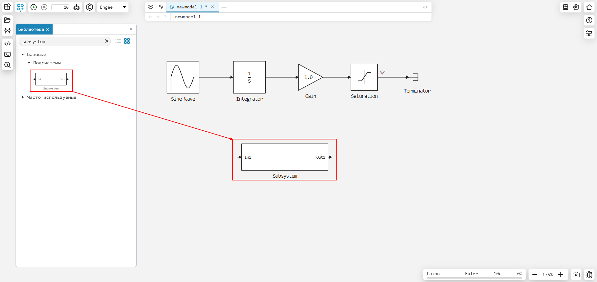
Add a block Subsystem from the block library, double-click on it with the left mouse button (so you will enter the subsystem) and add the necessary blocks in the standard way.
-
Select the blocks that you want to add to the subsystem with the key pressed Shift, click on the dots that appear in the corner of the rectangle and click on the icon
 Subsystem.
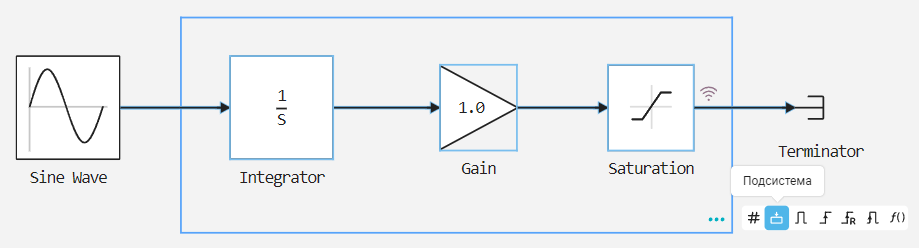
Within one subsystem, you can create an unlimited number of other subsystems located at different levels of nesting. As a result, the model has a hierarchy. To navigate through different levels of the model, use the Navigation bar.

Using the Model block
To work with model hierarchies, in addition to subsystems, you can use the block Model.
Unlike a subsystem, the contents of the Model block are a separate model and can be reused in other models (several models can refer to the Model block).
Therefore, you can include one model in another using the Model block. Each Model block is a reference to a particular model (submodel). Consider an example:
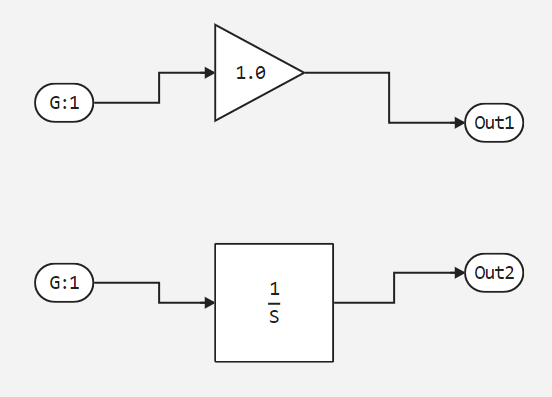
To create a submodel, use blocks In1, Gain, Integrator and Out1. The block parameters remain by default.
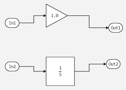
In the future, we plan to send the same signal to both input ports, so we use the Duplicate function for Inport blocks:
view of the model after converting the input ports
The resulting submodel looks like this:
Let’s save the submodel and set a name, in our case — newmodel_12. In the future, we will refer to this name in the parent model Model.
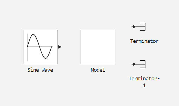
Next, we will create a model from which we will refer to the submodel. We use blocks Sine Wave, Model and Terminator.
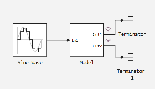
For the Sine Wave block, set the Sample time value to 0.1. The block will change. After that, right-click on the Model block and select Parameters. This will open the settings window, inside which we will refer to the previously created submodel newmodel_12:
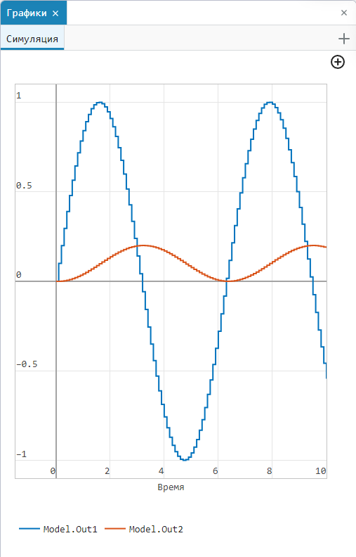
The Model block will change, input and output ports will appear, to which we will connect signal lines. For signals from the output ports, set the record:
Let’s run the simulation of the model and see the graph. We leave the solver by default (Euler). The sinusoidal signal simulation graph will be displayed in the window signal visualizations ![]() :
:
|