The system model of the physical layer of the DMR protocol
Modern digital radio communication systems require high reliability and efficiency of data transmission, especially if there are risks of data distortion and desynchronization. One of the key protocols used in professional mobile radio communications is DMR (Digital Mobile Radio), which provides digital voice and data transmission using efficient modulation and encoding techniques.
This project examines the system model of the DMR protocol, which includes a complete signal processing chain, from packet generation to demodulation and synchronization on the receiving side. Modeling of each stage of signal transmission allows analyzing the system's resistance to various types of interference and distortion.
The DMR protocol, like many other telecommunication standards, uses a layered architecture similar to the OSI (Open Systems Interconnection) model. The main levels of DMR can be divided as follows.
-
Physical Layer (PHY). It is responsible for transmitting and receiving bit streams over the radio channel and includes modulations (4-FSK, FM), filtering, synchronization and distortion correction in the channel (encoding also belongs to the physical layer, but we do not consider it in this example).
-
Data Link Layer (DLL). Provides reliable data transfer between nodes, manages access to the environment. It includes the generation of DMR packets, such as voice and signal data. This example demonstrates data packets. It can also include error control (CRC, FEC), logical channel management (TDMA, two slots), addressing (identification of subscribers and groups).
-
Network Layer. Provides routing and inter-network communication if the DMR is integrated into a larger system that includes the Internet.
-
In some implementations, there are additional layers: the transport layer (if DMR runs on top of IP) or, for example, the application Layer (Application Layer) – support for services (voice, text messages, telemetry).
The DMR standard focuses on the physical and channel layers, as they determine the operation of the radio channel. Network functions are more often implemented in infrastructure solutions (for example, in repeaters and control systems).
Enabling the auxiliary model launch function
function run_model( name_model)

    Path = (@__DIR__) * "/" * name_model * ".engee"

    if name_model in [m.name for m in engee.get_all_models()] # Checking the condition for loading a model into the kernel
        model = engee.open( name_model ) # Open the model
        model_output = engee.run( model, verbose=true ); # Launch the model
    else
        model = engee.load( Path, force=true ) # Upload a model
        model_output = engee.run( model, verbose=true ); # Launch the model
        engee.close( name_model, force=true ); # Close the model
    end
    sleep(5)
    return model_output
end
Running the model and analyzing the results
The model we have implemented includes the following key blocks.
-
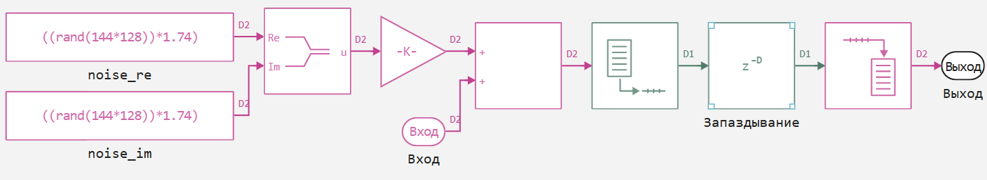
Packet generation is the formation of a signal sequence and empty blocks corresponding to the types of DMR packets.
-
4-FSK modulation is a digital modulation used in DMR to efficiently use the frequency band.
-
Raised cosine filter – used to limit the signal spectrum and minimize intersymbol interference.
-
FM modulator – conversion of a digital signal into an analog form for transmission over a radio channel.
-
Communication channel with simulated desynchronization – simulation of time mismatch between the transmitter and receiver.
-
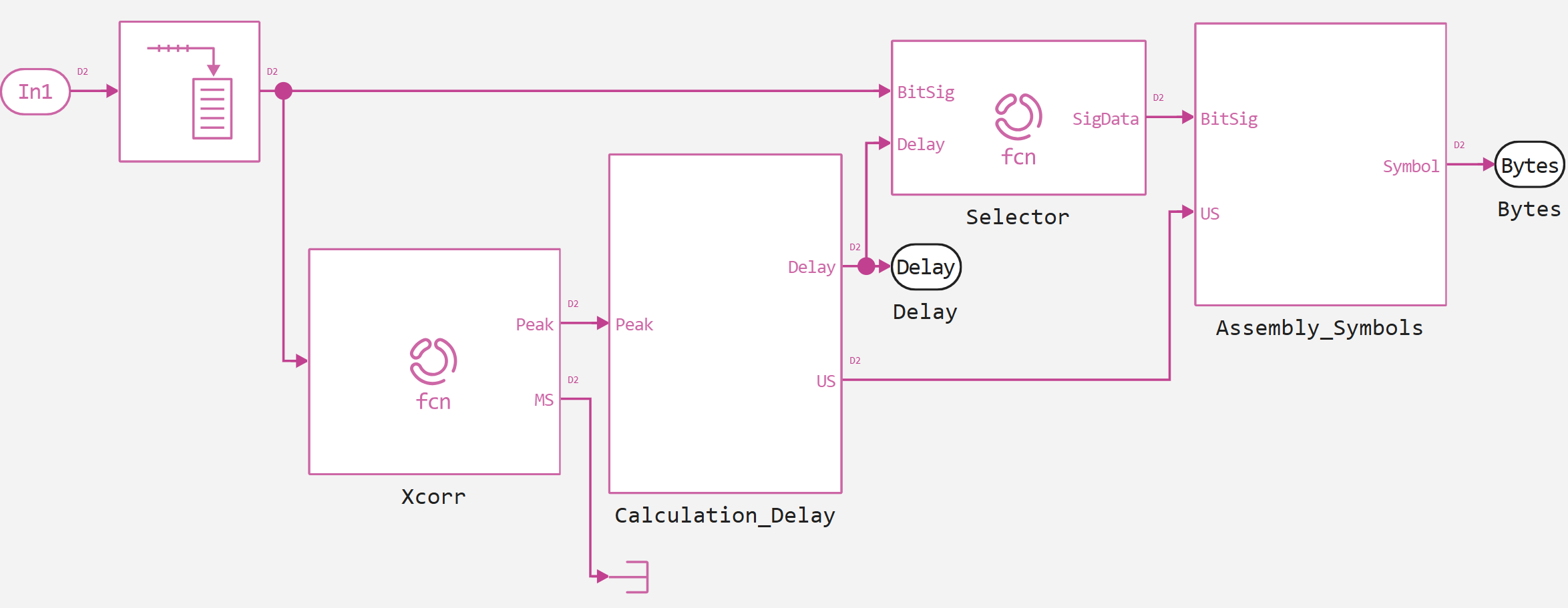
Signal sequence detection and frame synchronization – algorithms for restoring the temporary position of packets on the receiving side.
To test the correct transmission of messages in Russian and English, we will use pangrams in these two languages.
A pangram (from Greek — "all letters"), or a multi—letter, is a short text that uses all or almost all letters of the alphabet, if possible without repeating them.
We will set such a message, and also in the model we will represent it in byte form for convenience of interaction with the signal and supplement the messages with zeros to the number of elements in the vector, a multiple of 27 (216 data bits in one DMR packet). Part of the code from the model is shown below.
En = "Red fox jumps over the lazy dog"
Ru = "Eat some more of these soft French rolls, and drink some tea."
inp_sms = "$En. $Ru."
println("The input message:")
println(inp_sms)
println()
bytes = Int.(Vector{UInt8}(inp_sms))
remainder = length(bytes) % 27
bytes = vcat(bytes, remainder == 0 ? Int[] : zeros(Int, 27 - remainder))
println("Byte representation:")
println(bytes)
println()
println("Number of frames per message: $(length(bytes)/27)")
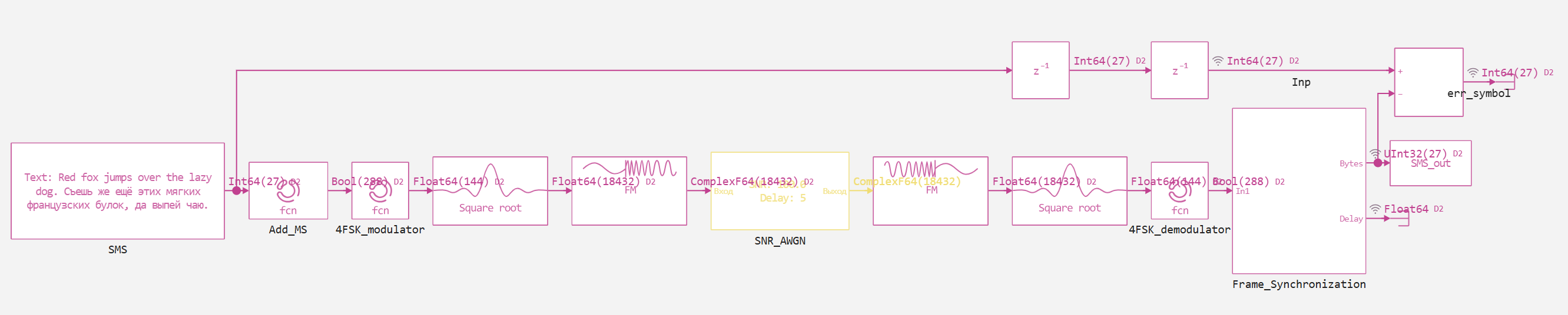
The screenshot below shows the entire implemented model.
Let's run our model at SNR = 25 in order to see the result with the least number of errors. If you are interested in the noise stability of the system, you can experiment with this parameter yourself.
snr = 25
run_model("DMR") # Launching the model.
Let's analyze the results. To begin with, we will display the byte representation of the input and output text messages, as well as the number of errors by byte.
println("SNR: $snr")
error_bytes = reduce(vcat,collect(simout["DMR/err_symbol"]).value)
println("Number of errors: $(sum(error_bytes.>0))")
Delay = reduce(vcat,collect(simout["DMR/Frame_Synchronization.Delay"]).value)
println("Bit delay: $(Int.(Delay[end]))")

Input = reduce(vcat,collect(simout["DMR/Inp"]).value)
plot(Input, seriestype = :steppre,  label = "Input")
Output = reduce(vcat,collect(simout["DMR/Out"]).value)
plot!(Output, seriestype = :steppre,  label = "Output")
As we can see, there are no errors at SNR = 25, and, therefore, we can accurately decode a text message.
SMS_sim = reduce(vcat, collect(SMS_out).value)
SMS = filter(x -> x != 0x00000000, SMS_sim)
SMS = String(UInt8.(SMS))
println("The restored string: ", SMS)  # Extra zeros are ignored.
Conclusion
In this example, the DMR system model is analyzed, affecting only the physical protocol layer. In the future, if the topic is of interest to the Community, we will look at other levels of this protocol and present the implementation of its various components.