Arduino Support Package: Pantograph project
Let's conduct a Pantograph experiment known in the circles of Arduino enthusiasts. Let's assemble a model that will control the position of the servo shaft based on the position of the rotary encoder.
Introduction
After mastering the Arduino Support Package documentation and using the basic integration blocks, you can start assembling the Pantograph experiment.
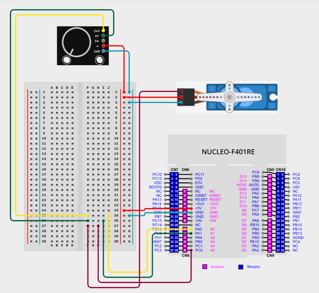
For this model, you will need a set of rotary encoder, servo, breadboard and STM32 Nucleo 64 F401RE.
Diagram on the layout
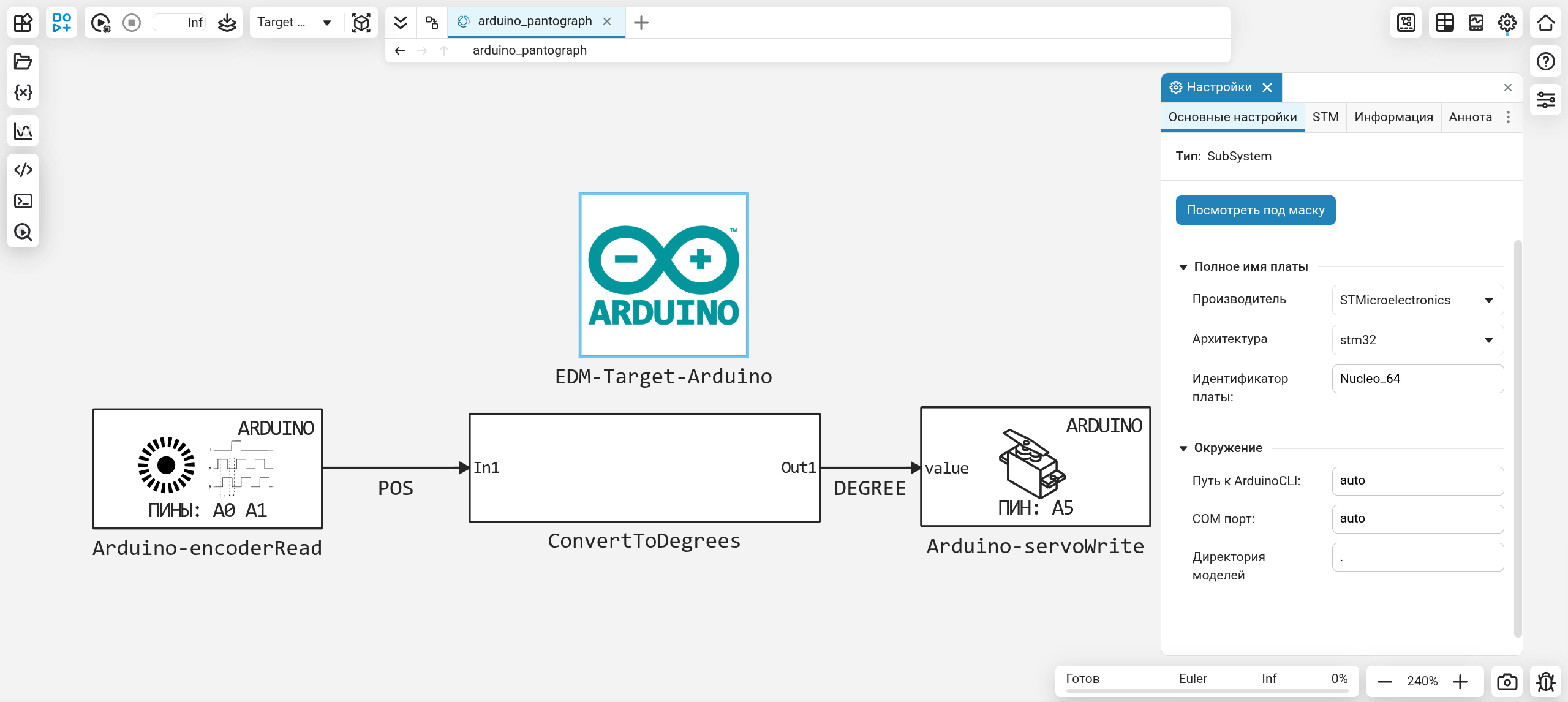
The Engee model
The whole logic of the model is to read the encoder position, convert this position to degrees, and transmit this value to the servo:
- Arduino-encoderRead - gets the value of the encoder position
- ConvertToDegrees - converts the encoder value to a value from the range from 0 to 180
- Arduino-servoWrite - sets the position of the servo shaft, based on the value from the ConvertToDegrees block
amplitude = 36 # The amplitude of the values for the encoder
POS - Value of the encoder shaft position
DEGREE - The value of degrees to set in the servo
The position of the encoder can take a value from -amplitude/2 before amplitude/2. In our case, it's from -18 before 18 what needs to be converted to the range from 0 to 180 is exactly what happens inside the ConvertToDegrees subsystem.:
.png)
BIASED = POS + (amplitude/2) # In the Add block
Shifting the interval by half the amplitude period.
MULTIPLIED = BIASED * 5 # In the DSP Product block
We stretch the resulting interval 5 times, getting a new one, the desired one from 0 to 180.
Conclusion
Using a simple example of a pantograph, we got acquainted with the capabilities of the Arduino-encoderRead and Arduino-servoWrite blocks, which allows us to create more complex control models.