网格;网格
|
该页面正在翻译中。 |
#
<无翻译>*马基科。网格;网格*-Function
mesh(x, y, z)
mesh(mesh_object)
mesh(x, y, z, faces)
mesh(xyz, faces)
绘制3D或2D网格。 支持 网格_对象s包括 网格;网格 类型从https://github.com/JuliaGeometry/GeometryBasics.jl[GeometryBasics.jl]。
地块类型
绘图类型别名 网格;网格 功能是 网格;网格.
例子:
简单网格图
using GLMakie
vertices = [
    0.0 0.0;
    1.0 0.0;
    1.0 1.0;
    0.0 1.0;
]

faces = [
    1 2 3;
    3 4 1;
]

colors = [:red, :green, :blue, :orange]

mesh(vertices, faces, color = colors, shading = NoShading)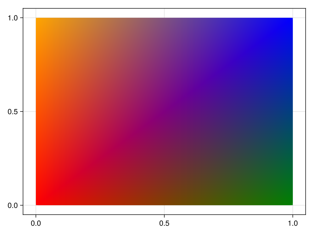
using GLMakie
vertices = Point3f[(1,0,0), (1,1,0), (0,1,0)]
faces1 = [1 2 3]
faces2 = [1 3 2]
colors = [:red, :green, :blue]

f = Figure(size = (800, 400))
ax = LScene(f[1,1], show_axis = false)
p = mesh!(ax, vertices, faces1, color = colors)
arrows!(ax, vertices, p.converted[1][].normal, lengthscale = 0.1, arrowsize = Vec3f(0.05, 0.05, 0.1), color = :orange)
text!(ax, vertices[faces1[:]], text = ["1", "2", "3"], align = (:center, :center), fontsize = 20, strokecolor = :white, strokewidth = 2, overdraw = true)

ax = LScene(f[1,2], show_axis = false)
p = mesh!(ax, vertices, faces2, color = colors)
arrows!(ax, vertices, p.converted[1][].normal, lengthscale = 0.1, arrowsize = Vec3f(0.05, 0.05, 0.1), color = :orange)
text!(ax, vertices[faces2[:]], text = ["1", "2", "3"], align = (:center, :center), fontsize = 20, strokecolor = :white, strokewidth = 2, overdraw = true)

f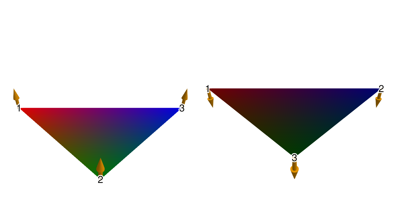
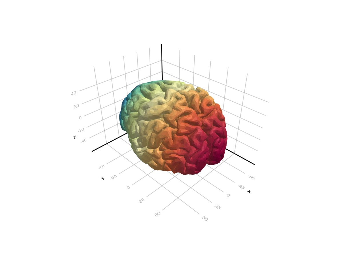
using GLMakie
using FileIO

brain = load(assetpath("brain.stl"))

mesh(
    brain,
    color = [tri[1][2] for tri in brain for i in 1:3],
    colormap = Reverse(:Spectral)
)
脸部颜色和法线
using GLMakie
using GeometryBasics

# Reduce quality of sphere
s = Tessellation(Sphere(Point3f(0), 1f0), 12)
ps = coordinates(s)
fs = faces(s)

#使用一个面观来处理一组新的面,每个面指一种颜色。
#每个面必须与fs中各自的面具有相同的长度。
#(使用相同的脸型保证了这一点)
FT=eltype(fs);N=长度(fs)
cs=FaceView(rand(RGBf,N),[FT(i)for i in1:N])

#每张脸生成法线(这也会创建一个视图)
ns=face_normals(ps,fs)

#创建网格
m=GeometryBasics。网格(ps,fs,normal=ns,color=cs)

网格(m)
使用GeometryBasics。网格和缓冲器/采样器类型
我们还可以创建一个网格来指定法线,uv坐标:
using GeometryBasics, LinearAlgebra, GLMakie, FileIO


# Create vertices for a Sphere
r = 0.5f0
n = 30
θ = LinRange(0, pi, n)
φ2 = LinRange(0, 2pi, 2 * n)
x2 = [r * cos(φv) * sin(θv) for θv in θ, φv in φ2]
y2 = [r * sin(φv) * sin(θv) for θv in θ, φv in φ2]
z2 = [r * cos(θv) for θv in θ, φv in 2φ2]
points = vec([Point3f(xv, yv, zv) for (xv, yv, zv) in zip(x2, y2, z2)])

# The coordinates form a matrix, so to connect neighboring vertices with a face
# we can just use the faces of a rectangle with the same dimension as the matrix:
_faces = decompose(QuadFace{GLIndex}, Tessellation(Rect(0, 0, 1, 1), size(z2)))
# Normals of a centered sphere are easy, they're just the vertices normalized.
_normals = normalize.(points)

# Now we generate UV coordinates, which map the image (texture) to the vertices.
# (0, 0) means lower left edge of the image, while (1, 1) means upper right corner.
function gen_uv(shift)
    return vec(map(CartesianIndices(size(z2))) do ci
        tup = ((ci[1], ci[2]) .- 1) ./ ((size(z2) .* shift) .- 1)
        return Vec2f(reverse(tup))
    end)
end

# We add some shift to demonstrate how UVs work:
uv = gen_uv(0.0)
# We can use a Buffer to update single elements in an array directly on the GPU
# with GLMakie. They work just like normal arrays, but forward any updates written to them directly to the GPU
uv_buff = Buffer(uv)
gb_mesh = GeometryBasics.Mesh(points, _faces; uv = uv_buff, normal = _normals)

f, ax, pl = mesh(gb_mesh,  color = rand(100, 100), colormap=:blues)
wireframe!(ax, gb_mesh, color=(:black, 0.2), linewidth=2, transparency=true)
record(f, "uv_mesh.mp4", LinRange(0, 1, 100)) do shift
    uv_buff[1:end] = gen_uv(shift)
end超出边界的uv坐标将在默认情况下重复。 人们可以使用一个 取样器 反对改变这种行为:
#=
Possible values:
:clamp_to_edge (default)
:mirrored_repeat
:repeat
=#
data = load(Makie.assetpath("earth.png"))
color = Sampler(rotl90(data'), x_repeat=:mirrored_repeat,y_repeat=:repeat)
f, ax, pl = mesh(gb_mesh,  color = color)
wireframe!(ax, gb_mesh, color=(:black, 0.2), linewidth=2, transparency=true)

record(f, "uv_mesh_mirror.mp4", LinRange(0, 1, 100)) do shift
    uv_buff[1:end] = gen_uv(shift)
end体积纹理
可以将3d数组传递给 `网格(args…;颜色=体积),并通过uvw坐标索引体积。 下面是一个交互式卷切片查看器的示例:
using GLMakie, GeometryBasics, NIfTI
brain = Float32.(niread(Makie.assetpath("brain.nii.gz")).raw)
# Define the positions
positions = Observable([Point3f(0.5, 0, 0), Point3f(0.5, 1, 0), Point3f(0.5, 1, 1), Point3f(0.5, 0, 1)])
triangles = GLTriangleFace[(1, 2, 3), (3, 4, 1)]

# We will stay in the unit cube, so the uv coordinates are just the positions.
uv_mesh = map((p) -> GeometryBasics.Mesh(p, triangles; uv=Vec3f.(p)), positions)
# Pass the volume plot to the color
f, ax, pl = mesh(uv_mesh, color=brain, shading=NoShading, axis=(; show_axis=false))
# Visualize the unit cube in which the volume lives
wireframe!(ax, Rect3f(Vec3f(0), Vec3f(1)), transparency=true, color=(:gray, 0.5))
cam = cameracontrols(ax.scene)
# Only rotate when left + alt buttons are pressed, so we can better interact with the slice
cam.controls.rotation_button = Mouse.left & Keyboard.left_alt
# Have colors for each point, so we can highlight it on hover
colors = Observable(fill(:black, 4))
ms = meshscatter!(ax, positions, markersize=0.05, color=colors)
# Also plot the volume next to it with a maximum intensity projection.
Makie.volume(f[1, 2], brain)

# Use mouseevents for drag events etc.
m_events = addmouseevents!(ax.scene)
point_idx = Ref(0)
point_start = Ref(Point3f(0))
clear_color() = if any(x -> x == :red, colors[])
    colors[] .= :black
    notify(colors)
end
# Define the handler for handling drag events to move the slice and
# highlight hovered points.
onany(ax.scene.events.mouseposition, m_events.obs) do mp, event
    if event.type == Makie.MouseEventTypes.leftdragstart
        p, idx = Makie.pick(ax.scene)
        if p == ms
            point_idx[] = idx
            colors[][idx] = :red
            point_start[] = positions[][idx]
            notify(colors)
        else
            point_idx[] = 0
        end
    elseif event.type == Makie.MouseEventTypes.leftdrag
        if point_idx[] != 0
            ray = Makie.ray_at_cursor(ax.scene)
            p = point_start[]
            line_start = Point3f(0, p[2], p[3])
            line_end = Point3f(1, p[2], p[3])
            new_point = Makie.closest_point_on_line(line_start, line_end, ray)
            positions[][point_idx[]] = new_point
            notify(positions)
        end
    elseif event.type == Makie.MouseEventTypes.leftdragstop
        point_idx[] = 0
        clear_color()
    elseif event.type == Makie.MouseEventTypes.over
        p, idx = Makie.pick(ax.scene)
        if p == ms
            if colors[][idx] != :red
                colors[][idx] = :red
                notify(colors)
            end
        else
            clear_color()
            point_idx[] = 0
        end
    end
end
f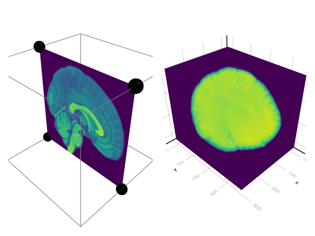
复杂网格(实验)
using GLMakie
using FileIO

# Load a mesh with material information. This will produce a GeometryBasics.MetaMesh
sponza = load(assetpath("sponza/sponza.obj"))

# The MetaMesh contains a standard GeometryBasics.Mesh in `sponza.mesh` with
# `mesh.views` defining the different sub-meshes, and material metadata in the
# `sponza.meta` Dict. The metadata includes:
# - meta[:material_names] which maps each view in `mesh.views` to a material name
# - meta[:materials] which maps a material name to a nested Dict of the loaded properties
# When a MetaMesh is given to Makie.mesh(), it will look for these entries and
# try to build a plot accordingly.
f, a, p = mesh(sponza)

# Set up camera
update_cam!(a.scene, Vec3f(-15, 7, 1), Vec3f(3, 5, 0), Vec3f(0,1,0))
cameracontrols(a).settings.center[] = false # don't recenter on display
cameracontrols(a).settings.fixed_axis[] = false # rotate freely
f
属性
夹式飞机
默认值为 自动的
剪辑平面提供了一种在3D空间中进行剪辑的方法。 您可以设置最多8个向量 平面3f 飞机在这里,后面的情节将被裁剪(即变得不可见)。 默认情况下,剪辑平面继承自父绘图或场景。 您可以删除父 夹式飞机 通过传递 平面3f[].
颜色
默认值为 @继承patchcolor
设置网格的颜色。 可以是一个 向量资料{<:Colorant} 对于每个顶点颜色或单个 着色剂. A 矩阵{<:Colorant} 可用于用纹理为网格着色,该纹理要求网格包含纹理坐标。 A <:抽象模式 可用于将重复的像素采样图案应用于网格,例如用于阴影。
颜色表
默认值为 @继承colormap:viridis
设置为数字采样的颜色表 颜色s. PlotUtils.cgrad(。..), 麦琪反向(any_colormap) 也可以使用,或者来自ColorBrewer或PlotUtils的任何符号。 要查看所有可用的颜色渐变,您可以调用 麦琪可用_gradients().
底纹/底纹
默认值为 自动的
设置使用的照明算法。 选项是 NoShading (无照明), 快装,快装 (AmbientLight+PointLight)或 MultiLightShading (多个灯,仅GLMakie)。 请注意,这不会影响RPRMakie。