upfirdn
Increasing the sampling rate, using an FIR filter, and lowering the sampling rate.
| Library |
|
Arguments
Input arguments
# xin — input signal
+
vector | the matrix
Details
An input signal specified as a vector or matrix. If xin If it is a vector, then it represents a single signal. If xin — matrix, then each column is filtered independently. For more information, see Recommendations.
| Data types |
|
# h — pulse response
+
vector | the matrix
Details
The impulse response of the filter, specified as a vector or matrix. If h — vector, then it represents one FIR filter. If h — matrix, then each column represents the impulse response of a separate FIR filter. For more information, see Recommendations.
| Data types |
|
#
p is
the sampling rate boost
factor
1 (default) | a positive integer
Details
The sampling rate boost factor, set as a positive integer.
| Data types |
|
#
q is
the sampling rate reduction
factor
1 (by default) | a positive integer
Details
The sampling rate reduction factor, set as a positive integer.
| Data types |
|
Examples
Converting the DAT sampling rate to the CD sampling rate
Details
Let’s change the sampling frequency of the signal using a rational conversion factor from the sampling frequency DAT 48 kHz to CD sampling rate 44.1 kHz. Using the function rationalize let’s find the numerator L and the denominator M the rational coefficient.
import EngeeDSP.Functions: upfirdn, kaiserord, fir1, kaiser

Fdat = 48e3
Fcd = 44.1e3
r = rationalize(Fcd/Fdat)
L = numerator(r)
M = denominator(r)

println("L=",L,", M=",M)
L=147, M=160Generate a sinusoid with frequency 1.5 kHz with sampling period equal 0.25 C. Let’s plot the first millisecond of the signal.
t = 0:1/Fdat:0.25-1/Fdat
x = sin.(2π * 1.5e3 * t)
scatter(t, x, markershape=:circle, markersize=3, line=:stem, label="signal")
xlims!(0, 0.001)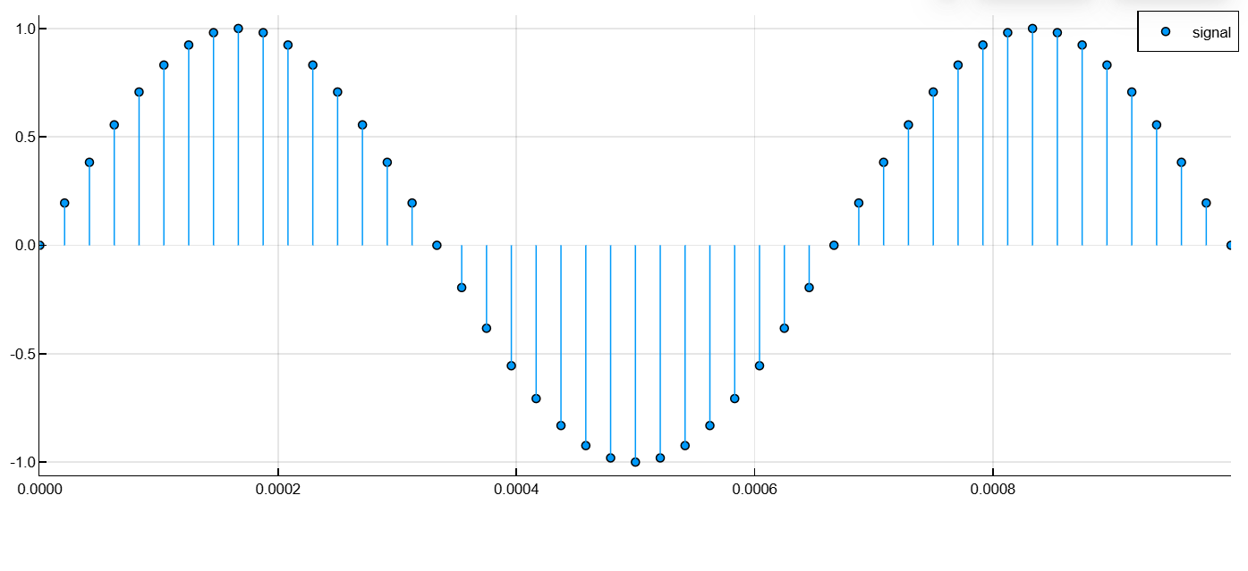
Let’s design a low-pass filter with smoothing using the Kaiser window. Let’s set the boundaries of the filter band at 90% and 110% of the cutoff frequency, . Setting the ripple in the bandwidth 5 dB and attenuation in the delay band 40 dB. Let’s set the gain in the bandwidth to L.
Fs = 48e3
f = (Fdat/2) * min(1/L, 1/M)

Wp = 0.9*f / (Fs/2)
Ws = 1.1*f / (Fs/2)
Rp = 5
Rs = 40

n, Wn, beta = kaiserord([Wp, Ws], [1, 0], [10^(-Rp/20), 10^(-Rs/20)])
b = fir1(n, Wn, kaiser(n+1, beta))
h = L * b
Using the function upfirdn with a filter h to resample the sine wave. Calculate and compensate for the delay introduced by the filter. We will generate the corresponding oversampled time vector.
y = upfirdn(x, h, L, M)

delay_float = ((length(h) - 1) / 2 - (L - 1)) / L
delay = floor(Int, delay_float)
y = y[delay+1:end]


t_res = (0:length(y)-1) / Fcd
Let’s display the original and oversampled signal on the graph.
plot(t, x, line=:stem, marker=:circle, markersize=2,
     label="Original (48 kHz)", color=:red,
     xlims=(0, 0.001), title="Signal Comparison",
     xlabel="Time (s)", ylabel="Amplitude")

scatter!(t_res, y, markershape=:circle, markersize=2,
         label="Resampled (44.1 kHz)", color=:blue)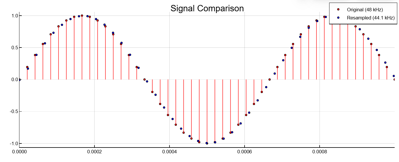
Recommendations
-
xin— vector andh— vector.There is one filter and one signal at the input, so the function collapses
xinwithh. The output signalyoutis a string vector ifxin— vector-string; otherwiseyout— column vector. -
xin— the matrix, andh— vector.There is one filter and many signals at the input, so the function collapses
hwith each columnxin. The resultingyout— a matrix with the same number of columns asxin. -
xin— vector, ehh— the matrix.There are several filters and one signal at the input, so the function collapses each column.
hwithxin. The resultingyout— a matrix with the same number of columns ash. -
xin— the matrix andh— a matrix, both with the same number of columns.There are several filters and several signals at the input, so the function collapses the corresponding columns.
xinandh. The resultingyout— a matrix with the same number of columns asxinandh.
Algorithms
Function upfirdn uses a polyphase interpolation structure. The number of multiplication-summation operations in a polyphase structure is approximately equal to , where and — lengths and accordingly. For long signals, this formula is often accurate.
Function upfirdn performs a cascade of three operations:
-
Increasing the sampling rate of the input data in the matrix
xinby an integer coefficientp(adding zeros). -
FIR filtering for a signal with an increased sampling frequency with a sequence of pulse characteristics specified as a vector or matrix
h. -
Lowering the sampling rate by an integer factor
q(dropping counts).
Literature
-
Crochiere, R. E. A General Program to Perform Sampling Rate Conversion of Data by Rational Ratios. Programs for Digital Signal Processing (Digital Signal Processing Committee of the IEEE Acoustics, Speech, and Signal Processing Society, eds.). New York: IEEE Press, 1979, Programs 8.2-1–8.2-7.
-
Crochiere, R. E., and Lawrence R. Rabiner. Multirate Digital Signal Processing. Englewood Cliffs, NJ: Prentice-Hall, 1983.