Average-Value Inverter (Three-Phase)
An average DC voltage converter to a three-phase AC voltage with a fixed power loss.
blockType: AcausalElectricPowerSystems.Converters.ThreePhaseAverageValueInverter
|
Path in the library: |

Description
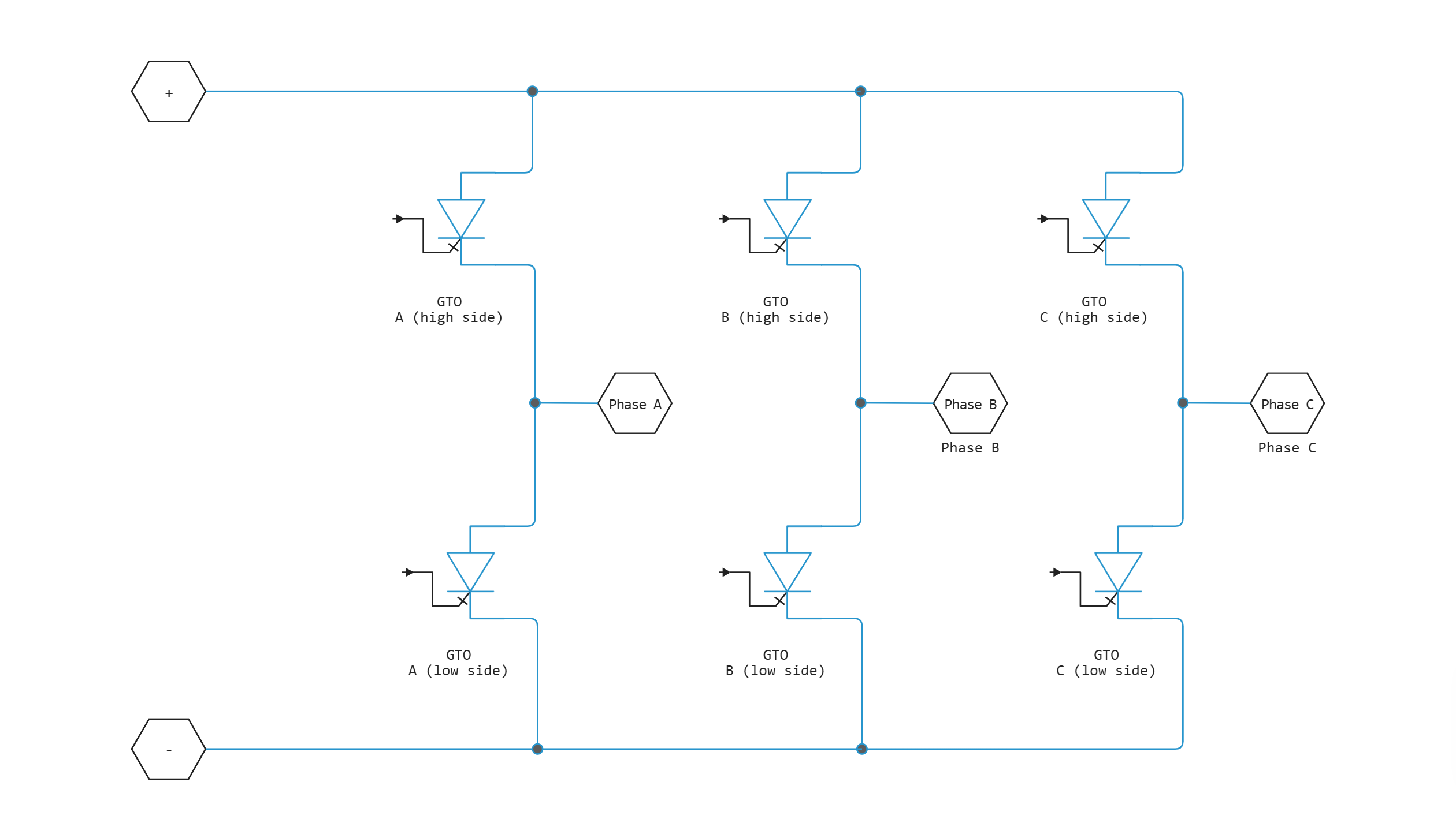
Block Average-Value Inverter (Three-Phase) simulates an average full-period inverter. It converts DC voltage to three-phase AC voltage and the power consumption of three-phase AC current to DC power consumption. The corresponding DC power consumption is equal to the sum of the fixed power loss and the AC power consumption.
Block Average-Value Inverter (Three-Phase) It can only be used as a full-cycle inverter. It behaves like an AC voltage source controlled by a DC voltage. The ratio you set determines the ratio between DC and AC voltages.
The figure shows an equivalent circuit of a full-period inverter. However, the block Average-Value Inverter (Three-Phase) it does not produce harmonics, which are usually associated with a detailed representation, because it performs an average power conversion.
Equations defining electrical parameters
The voltages are determined as follows:
where
-
and — voltage at the positive and negative terminals of the inverter;
-
— the voltage difference between the positive and negative terminals of the inverter;
-
— DC offset;
-
— the ratio of the rated AC voltage to the rated DC voltage of the inverter; see parameter Ratio of rated AC voltage to rated DC voltage for values for common inverter control modes;
-
— current AC line voltage;
-
— peak phase voltage;
-
— frequency;
-
— time;
-
— phase shift;
-
, , — the corresponding phase voltage of alternating current.
Power, resistance, and currents are determined by the following ratios
where
-
, , — the corresponding alternating currents flowing through the inverter;
-
— output power on the AC side; has a minimum limit
0Tue; -
— the fixed power loss specified in the block;
-
— resistance on the DC side;
-
— the current flowing between the positive and negative terminals of the inverter.
The inverter starts generating AC voltage, that is, it turns on when the voltage of the DC source exceeds the value set for the parameter DC voltage for turn on. It stops the conversion, that is, it turns off when the voltage of the DC source drops below the value set for the parameter DC voltage for turn off. When the inverter is turned off, the unit sets the output alternating current to zero.
Ports
Conserving
#
+
—
positive terminal
electricity
Details
The port connected to the positive terminal.
| Program usage name |
|
#
−
—
negative terminal
electricity
Details
The port connected to the negative terminal.
| Program usage name |
|
#
~
—
three-phase port
electricity
Details
Composite three-phase port.
| Program usage name |
|
Parameters
Parameters
# Ratio of rated AC voltage to rated DC voltage — the ratio of the rated AC voltage to the rated DC voltage
Details
The table shows the ratios for common control modes of a three-phase two-level inverter. The default value is .
For conduction modes 180° and 120° The set voltages represent the fundamental operating values of the interfacial voltages. For other methods, these voltages represent the maximum fundamental effective values of the interfacial stresses.
You can control the output voltage of the inverter according to specific requirements. The number of PSYM modes includes 30° PSYM, 60° PSYM and 120° LET’S GO. For more information, see the literature [3], [4].
| Management method | (line-line) | Relationship (line-line) to |
|---|---|---|
Conduction mode |
|
|
Conduction mode |
|
|
Hysteresis current control [2] |
|
|
Sinusoidal PWM [2] |
|
|
Spatial vector modulation (PVM) [2] |
|
|
|
|
|
Convert to the original AC voltage of the averaged rectifier |
|
|
| Default value |
|
| Program usage name |
|
| Evaluatable |
Yes |
#
Phase shift —
phase shift
rad | deg | rev | mrad | arcsec | arcmin | gon
Details
Phase shift in angular units.
| Units |
|
| Default value |
|
| Program usage name |
|
| Evaluatable |
Yes |
#
DC voltage for turn on —
DC voltage to turn on
V | uV | mV | kV | MV
Details
When the DC power supply voltage exceeds this value, the inverter generates an AC output voltage.
| Units |
|
| Default value |
|
| Program usage name |
|
| Evaluatable |
Yes |
#
DC voltage for turn off —
DC voltage to turn off
V | uV | mV | kV | MV
Details
When the voltage of the DC source drops below this value, the inverter turns off and the unit sets the output alternating currents to zero.
| Units |
|
| Default value |
|
| Program usage name |
|
| Evaluatable |
Yes |
#
Rated AC frequency —
frequency of alternating current in Hz
Hz | kHz | MHz | GHz
Details
The frequency of the alternating current, set in Hz (where Hz is defined as 1/s). For example, kHz and MHz are acceptable units of measurement, but rad/s are not.
| Units |
|
| Default value |
|
| Program usage name |
|
| Evaluatable |
Yes |
#
Fixed power loss —
fixed power loss
W | uW | mW | kW | MW | GW | V*A | HP_DIN
Details
The minimum power consumed on the DC side. Default value — 1e3.
| Units |
|
| Default value |
|
| Program usage name |
|
| Evaluatable |
Yes |
Literature
-
Rashid, M. H. Pulse-Width-Modulation Inverters. Upper Saddle River, NJ: Prentice-Hall, 2004, pp. 237–248.
-
Krause, P. C., O. Wasynczuk, and S. D. Sudhoff. Analysis of Electric Machinery and Drive Systems. Piscataway, NJ: IEEE Press, 2002.
-
Chung, D. W., J. S. Kim, and S. K. Kul. «Unified voltage modulation technique for real-time three-phase power conversion.» IEEE Transactions on Industry Applications. Vol. 34, no. 2, 1998, pp. 374–380.
-
Hava, A. M., R. J. Kerkman, and T. A. Lipo. «Simple analytical and graphical methods for carrier-based PWM-VSI drives.» IEEE Transactions on Power Electronics. Vol. 14, 1999, no. 1, pp. 49–61.