Rectifier (Three-Phase)
Conversion of three-phase AC voltage to DC voltage.
blockType: AcausalElectricPowerSystems.Converters.ThreePhaseRectifier
|
Path in the library: |

Description
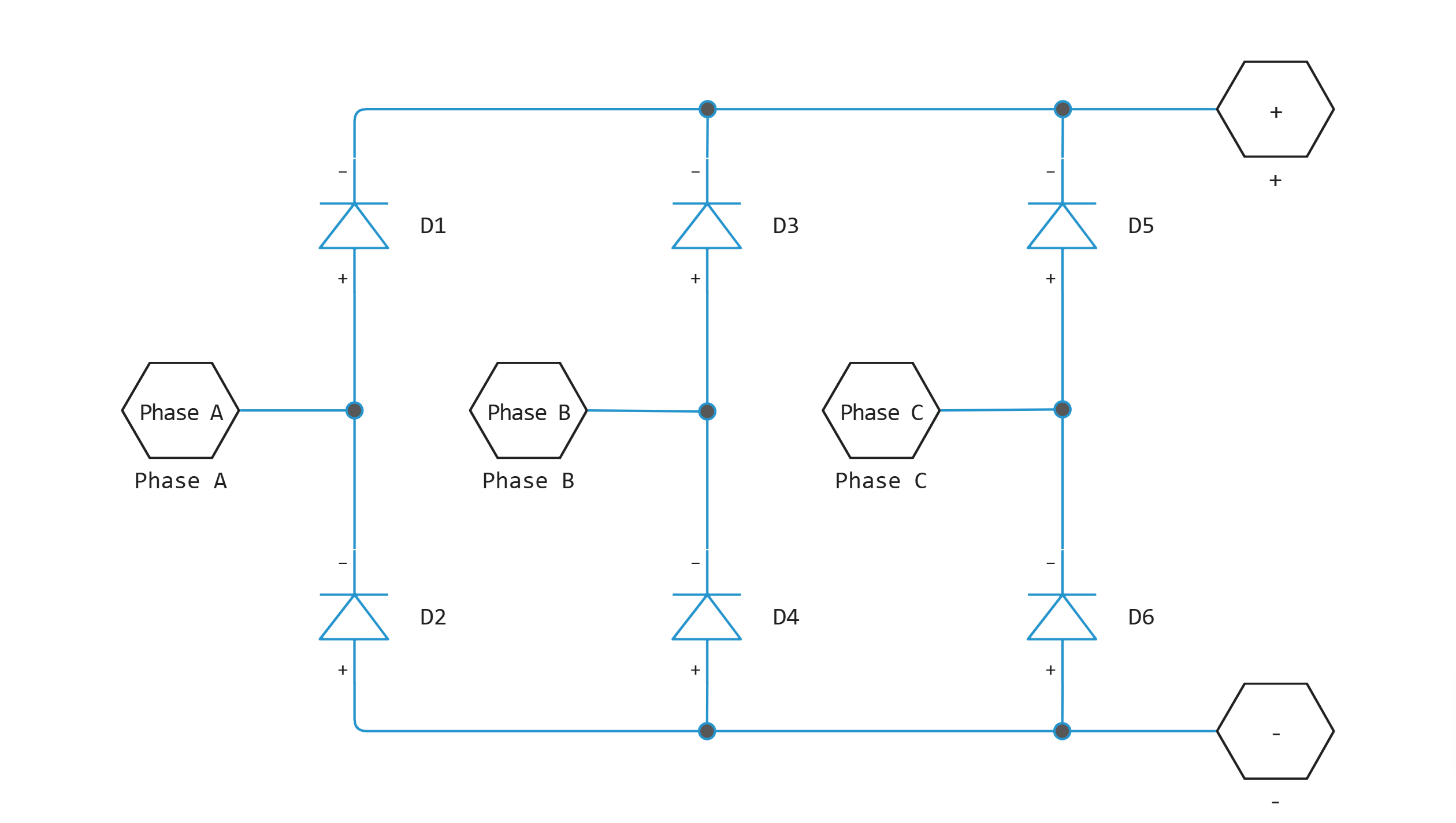
Block Rectifier (Three-Phase) Simulates a three-beam diode bridge circuit that converts a three-phase AC voltage to a DC voltage. The figure shows an equivalent circuit of a three-beam diode bridge.
In the parameters group Charge Dynamics You can select the type of diode to be used in the three-shoulder bridge circuit. The table shows how to configure the parameter Model dynamics depending on your goals.
| Goal | Value for selection | Block operation |
|---|---|---|
Prioritize simulation speed |
|
Each arm of the bridge circuit uses a block Diode. The block dialog box does not display additional parameters. |
Accurately indicate the charge dynamics in reverse mode |
|
Each arm of the bridge circuit uses a block with charge dynamics settings Diode. The block dialog box displays the parameters related to the block’s switching model. |
Ports
Conserving
#
+
—
positive terminal
electricity
Details
The port connected to the positive terminal.
| Program usage name |
|
#
–
—
negative terminal
electricity
Details
The port connected to the negative terminal.
| Program usage name |
|
#
~
—
Three-phase port
electricity
Details
Input three-phase port.
| Program usage name |
|
Parameters
Main
#
Off conductance —
closed junction conductivity
S | nS | uS | mS | 1/Ohm
Details
The conductivity of each reverse-biased diode.
| Units |
|
| Default value |
|
| Program usage name |
|
| Evaluatable |
Yes |
#
Forward voltage —
forward voltage
V | uV | mV | kV | MV
Details
The minimum voltage required at the + and – ports of each diode so that the slope of the volt-ampere characteristic of the diode is equal to , where — parameter value On resistance.
| Units |
|
| Default value |
|
| Program usage name |
|
| Evaluatable |
Yes |
#
On resistance —
resistance to open transition
Ohm | mOhm | kOhm | MOhm | GOhm
Details
The rate of voltage change relative to the current is higher than the forward voltage for each diode.
| Units |
|
| Default value |
|
| Program usage name |
|
| Evaluatable |
Yes |
Charge Dynamics
#
Rate of change of current when measuring iRM —
the rate of change of current during iRM measurement
A/s | A/us
Details
The rate of change of the current when measuring the peak reverse current. This value must be less than zero.
Dependencies
To use this parameter, set for the parameter Model dynamics meaning Diode with charge dynamics.
| Units |
|
| Default value |
|
| Program usage name |
|
| Evaluatable |
Yes |
#
Junction capacitance —
transfer capacity
F | pF | nF | uF | mF
Details
The capacity of the diode junction.
Dependencies
To use this parameter, set for the parameter Model dynamics meaning Diode with charge dynamics.
| Units |
|
| Default value |
|
| Program usage name |
|
| Evaluatable |
Yes |
#
Initial forward current when measuring iRM —
initial forward current during iRM measurement
A | pA | nA | uA | mA | kA | MA
Details
The initial forward current when measuring the peak reverse current. This value must be greater than zero.
Dependencies
To use this parameter, set for the parameter Model dynamics meaning Diode with charge dynamics.
| Units |
|
| Default value |
|
| Program usage name |
|
| Evaluatable |
Yes |
# Reverse recovery time stretch factor — the stretching coefficient of the reverse recovery time
Details
The value that the block uses for calculation Reverse recovery time, trr. This value must be greater than `1'. Specifying the stretching coefficient is an easier way to parameterize the reverse recovery time than specifying the reverse recovery charge. The higher the value of the stretching coefficient, the longer it takes for the reverse recovery current to dissipate.
Dependencies
To use this parameter, set for the parameter Model dynamics meaning Diode with charge dynamics, and for the parameter Reverse recovery time parameterization meaning Specify stretch factor.
| Default value |
|
| Program usage name |
|
| Evaluatable |
Yes |
#
Reverse recovery time parameterization —
type of reverse recovery time determination
Specify stretch factor | Specify reverse recovery time directly | Specify reverse recovery charge
Details
Defines the method for setting the reverse recovery time in the block. The default value is Specify reverse recovery time directly.
When selecting a value Specify stretch factor or Specify reverse recovery charge you specify the value that the block uses to calculate the reverse recovery time.
Dependencies
To use this parameter, set for the parameter Model dynamics meaning Diode with charge dynamics.
| Values |
|
| Default value |
|
| Program usage name |
|
| Evaluatable |
No |
#
Reverse recovery time, trr —
reverse recovery time
s | ns | us | ms | min | hr | d
Details
The interval between the moment when the current initially passes through zero (when the diode turns off) and the moment when the current drops to less than 10% of the peak reverse current. Parameter value Reverse recovery time, trr there must be more than the parameter value. Peak reverse current, iRM, divided by the parameter value Rate of change of current when measuring iRM.
Dependencies
To use this parameter, set for the parameter Model dynamics meaning Diode with charge dynamics, and for the parameter Reverse recovery time parameterization meaning Specify reverse recovery time directly.
| Units |
|
| Default value |
|
| Program usage name |
|
| Evaluatable |
Yes |
#
Peak reverse current, iRM —
peak reverse current
A | pA | nA | uA | mA | kA | MA
Details
The peak return current measured by the external test circuit. This value must be less than zero.
Dependencies
To use this parameter, set for the parameter Model dynamics meaning Diode with charge dynamics.
| Units |
|
| Default value |
|
| Program usage name |
|
| Evaluatable |
Yes |
#
Reverse recovery charge, Qrr —
reverse recovery charge
C | nC | uC | mC | nA*s | uA*s | mA*s | A*s | mA*hr | A*hr | kA*hr | MA*hr
Details
The value that the block uses to calculate the parameter Reverse recovery time, trr. Use this parameter if the reverse recovery charge value is specified in the block parameters as the type of reverse recovery time determination instead of the reverse recovery time value.
The reverse recovery charge is the total charge that continues to dissipate after the diode is turned off. The value must be less than ,
where
-
— the value specified for the parameter Peak reverse current, iRM;
-
— the value specified for the parameter Rate of change of current when measuring iRM.
Dependencies
To use this parameter, set for the parameter Model dynamics meaning Diode with charge dynamics, and for the parameter Reverse recovery time parameterization meaning Specify reverse recovery charge.
| Units |
|
| Default value |
|
| Program usage name |
|
| Evaluatable |
Yes |
#
Model dynamics —
dynamics of the diode charge
Diode with no dynamics | Diode with charge dynamics
Details
The dynamics of the diode charge. The default value is Diode with no dynamics.
The following charge dynamics options are possible:
-
Diode with no dynamics -
Diode with charge dynamics
| Values |
|
| Default value |
|
| Program usage name |
|
| Evaluatable |
No |