PDUs in DMR
In modern professional radio communication systems such as DMR (Digital Mobile Radio), the interaction between the base station (BS) and the subscriber radio station (RS) is a strictly regulated and highly organized process. This is necessary to ensure reliable, noise-resistant and efficient communication of multiple subscribers within a single channel.
The BS acts as a coordinator and managing center in its coverage area (sote). It continuously transmits service information, synchronizing all PCs in the network, managing channel access and providing communication services. The radio station (RS), in turn, for any of its actions (starting a call, transmitting voice or data, registering on the network) must interact with the BS by requesting resources and following its instructions.
This interaction is carried out by exchanging special data packets strictly corresponding to the DMR frame format. One of the key structures for organizing such a dialogue is the data slot, the main element of which is the PDU (Protocol Data Unit).
A SLOT PDU is an information part of a slot designed to transmit signal information or user data. Its structure includes several critical information elements that allow BS and RS to correctly interpret the transmitted information. The composition of the SLOT PDU for the alarm message can be represented by the following table:
| Information Element (IE) | Length (bits) | Note |
|---|---|---|
| Color Code (CC) | 4 | The unique identifier of the service area (cell). Allows radio stations to distinguish their base station from others operating on the same frequency (for example, in a neighboring cell). The PC ignores messages with an incorrect CC. |
| Data type | 4 | Defines the type and purpose of the information transmitted to the PDU. For example, whether the message is a connection request, a user data packet, or a service command. |
| Slot type parity | 12 | The service field, which is the FEC Golley code (20.8). It is used to control and correct errors in the first two fields (CC and Data Type). It allows the recipient to detect and correct possible errors made during transmission, ensuring high reliability of receiving critical signal information. |
The principle of operation by example:
-
Call Initiation (PC -> BS):
- The radio station (PC) wants to establish a connection. It forms a SLOT PDU in which it installs:
- Color Code (CC) according to the target base station code.
- Data type to the value corresponding to the connection request (for example,
[0,0,1,0]).
- The radio station (PC) wants to establish a connection. It forms a SLOT PDU in which it installs:
- To these 8 bits (4+4) is added a 12-bit Slot type Parity (Gaulley FEC), forming a protected 20-bit block.
- This packet is transmitted to the BS.
-
Request Processing (BS):
- The base station receives the signal. First of all, it decodes a 20-bit block using the Gaulle code to check and correct errors in the CC and Data Type fields.
- BS checks the Color code. If it matches her own, she continues processing.
- BS analyzes Data type. Meaning
[0,0,1,0]indicates to her that this is a connection request. - Next, the BS, depending on the channel's occupancy, either allocates resources to this PC and sends it a response confirmation PDU with a different Data type, or rejects the request.
-
Data transmission:
- After establishing a connection for voice or user data transmission, the PC and BS will use the Data type ** reserved for this purpose in the SLOT PDU (for example,
[0,0,0,1]).
- After establishing a connection for voice or user data transmission, the PC and BS will use the Data type ** reserved for this purpose in the SLOT PDU (for example,
Thus, the contents of the SLOT PDU, namely the combination of the fields protected by the Gaulley code Color Code and Data type, is the fundamental mechanism that ensures the start, maintenance and termination of any communication session between the base station and the radio station in the DMR network.
As in all previous demos on the DMR topic, we continue to use our custom library of functions.:
include("/user/start/examples/communication/dmr_v3/dmr_lib.jl")
Let's see what's new in it.
1. Function typegen (extended version)
It has been modified and now accepts two input parameters:
CC(Color Code) is a 4-bit vector representing the color code of the system.data_type— A 4-bit vector that defines the type of data being transmitted (for example,[0,0,1,0]for the connection signal or[0,0,0,1]for user data).
The function combines these two vectors into one 8-bit block and applies noise-resistant coding to it using the Gaulle code (20.8). This code not only detects, but also corrects errors that occurred during transmission. The result of the function is a 20-bit secure block that is ready to be broadcast.
2. Function encode_slot_pdu
This function is a high-level wrapper for typegen. It takes the same arguments (color code and data type), calls typegen to generate a 20-bit block, it visually outputs the resulting bit sequence to the console. Its main task is to simplify the coding process and provide visual control of the result.
3. Function decode_slot_pdu
Performs the reverse operation. It takes a 20-bit vector as input (received by SLOT PDU) and divides it into its original components:
- The first 4 bits are interpreted as a color code (
CC_decoded). - The next 4 bits are as a data type (
data_type_decoded).
The function does not check for errors using the Gaulley code, but simply extracts information bits from the corresponding position in the slot structure.
function typegen(CC::Vector{Int}, data_type::Vector{Int})
    data = vcat(CC, data_type)

    ENCODE_2087 = [
        0x0000, 0xB08E, 0xE093, 0x501D, 0x70A9, 0xC027, 0x903A, 0x20B4, 0x60DC, 0xD052, 0x804F, 0x30C1, 0x1075, 0xA0FB, 0xF0E6,
        0x4068, 0x7036, 0xC0B8, 0x90A5, 0x202B, 0x009F, 0xB011, 0xE00C, 0x5082, 0x10EA, 0xA064, 0xF079, 0x40F7, 0x6043, 0xD0CD,
        0x80D0, 0x305E, 0xD06C, 0x60E2, 0x30FF, 0x8071, 0xA0C5, 0x104B, 0x4056, 0xF0D8, 0xB0B0, 0x003E, 0x5023, 0xE0AD, 0xC019,
        0x7097, 0x208A, 0x9004, 0xA05A, 0x10D4, 0x40C9, 0xF047, 0xD0F3, 0x607D, 0x3060, 0x80EE, 0xC086, 0x7008, 0x2015, 0x909B,
        0xB02F, 0x00A1, 0x50BC, 0xE032, 0x90D9, 0x2057, 0x704A, 0xC0C4, 0xE070, 0x50FE, 0x00E3, 0xB06D, 0xF005, 0x408B, 0x1096,
        0xA018, 0x80AC, 0x3022, 0x603F, 0xD0B1, 0xE0EF, 0x5061, 0x007C, 0xB0F2, 0x9046, 0x20C8, 0x70D5, 0xC05B, 0x8033, 0x30BD,
        0x60A0, 0xD02E, 0xF09A, 0x4014, 0x1009, 0xA087, 0x40B5, 0xF03B, 0xA026, 0x10A8, 0x301C, 0x8092, 0xD08F, 0x6001, 0x2069,
        0x90E7, 0xC0FA, 0x7074, 0x50C0, 0xE04E, 0xB053, 0x00DD, 0x3083, 0x800D, 0xD010, 0x609E, 0x402A, 0xF0A4, 0xA0B9, 0x1037,
        0x505F, 0xE0D1, 0xB0CC, 0x0042, 0x20F6, 0x9078, 0xC065, 0x70EB, 0xA03D, 0x10B3, 0x40AE, 0xF020, 0xD094, 0x601A, 0x3007,
        0x8089, 0xC0E1, 0x706F, 0x2072, 0x90FC, 0xB048, 0x00C6, 0x50DB, 0xE055, 0xD00B, 0x6085, 0x3098, 0x8016, 0xA0A2, 0x102C,
        0x4031, 0xF0BF, 0xB0D7, 0x0059, 0x5044, 0xE0CA, 0xC07E, 0x70F0, 0x20ED, 0x9063, 0x7051, 0xC0DF, 0x90C2, 0x204C, 0x00F8,
        0xB076, 0xE06B, 0x50E5, 0x108D, 0xA003, 0xF01E, 0x4090, 0x6024, 0xD0AA, 0x80B7, 0x3039, 0x0067, 0xB0E9, 0xE0F4, 0x507A,
        0x70CE, 0xC040, 0x905D, 0x20D3, 0x60BB, 0xD035, 0x8028, 0x30A6, 0x1012, 0xA09C, 0xF081, 0x400F, 0x30E4, 0x806A, 0xD077,
        0x60F9, 0x404D, 0xF0C3, 0xA0DE, 0x1050, 0x5038, 0xE0B6, 0xB0AB, 0x0025, 0x2091, 0x901F, 0xC002, 0x708C, 0x40D2, 0xF05C,
        0xA041, 0x10CF, 0x307B, 0x80F5, 0xD0E8, 0x6066, 0x200E, 0x9080, 0xC09D, 0x7013, 0x50A7, 0xE029, 0xB034, 0x00BA, 0xE088,
        0x5006, 0x001B, 0xB095, 0x9021, 0x20AF, 0x70B2, 0xC03C, 0x8054, 0x30DA, 0x60C7, 0xD049, 0xF0FD, 0x4073, 0x106E, 0xA0E0,
        0x90BE, 0x2030, 0x702D, 0xC0A3, 0xE017, 0x5099, 0x0084, 0xB00A, 0xF062, 0x40EC, 0x10F1, 0xA07F, 0x80CB, 0x3045, 0x6058, 0xD0D6
    ]
    byte = bi2de(data)
    cksum = ENCODE_2087[byte+1]
    type_val = (byte << 12) | ((cksum & 0xFF) << 4) | (cksum >> 8)
    type20bit = de2bi(type_val, 20)
    return type20bit
end

function encode_slot_pdu(CC::Vector{Int}, data_type::Vector{Int})
    slot_pdu = typegen(CC, data_type)
    println("Full SLOT PDU: $(join(slot_pdu))")
    return slot_pdu
end

function decode_slot_pdu(slot_pdu::Vector{Int})
    CC_decoded = slot_pdu[1:4]
    data_type_decoded = slot_pdu[5:8]
    return CC_decoded, data_type_decoded
end
Let's do a simple test of our new features to make sure they work correctly.
The logic of the test:
- We set the initial data: We determine the test values of the color code (CC) and the data type. In this case, both parameters are set to
[0, 0, 0, 1]. - We encode the data: Function
encode_slot_pduaccepts our initial data. Inside, it calls a functiontypegenwhich:
- Combines CC and the data type into an 8-bit sequence.
- Applies a complex noise-resistant coding algorithm (the Golley code) to it.
- This block is displayed on the screen, and we can see how our original 8 bits have turned into 20.
- Decode the data: We simulate the process of receiving data by transmitting the received 20-bit block to the function
decode_slot_pdu. Its task is to extract the initial information bits from this protected structure, that is, the first 4 bits (CC) and the next 4 bits (data type). - Compare the results.
CC = [0, 0, 0, 1]
data_type = [0, 0, 0, 1]

println("Initial data:")
println("Color code: $(join(CC))")
println("Data type: $(join(data_type))")
encoded_pdu = encode_slot_pdu(CC, data_type)
decoded_CC, decoded_data_type = decode_slot_pdu(encoded_pdu)

println("\Presults:")
println("Decoded CC: $(join(decoded_CC))")
println("Decoded data type: $(join(decoded_data_type))")

if (CC == decoded_CC) && (data_type == decoded_data_type)
    println("✅ SUCCESS: All the data matched!")
else
    println(" ERROR: The data did not match!")
end
The conducted test and subsequent modeling serve an important but intermediate purpose. As we can see from this test and understand from further work, the key task at the current stage is not a detailed and full—scale modeling of the DMR protocol with all its nuances.
Our main goal is to create and verify the correctness of the basic functionality, which will serve as a reliable foundation for the development of this series of demonstrations. We abstract away unnecessary complexity in order to:
- Focus on the key mechanisms (coding, slot structure) without overloading the details.
- Build a set of proven and working functions that can be confidently used and expanded in the following parts.
- This modular approach allows you to gradually add new layers of functionality (for example, voice codecs, various types of frames, multiple access mechanisms) in subsequent demonstrations without redoing the basic implementation.
Thus, the current implementation is a conceptual framework prepared for future expansion and deepening into the topic of digital radio communications.
Implemented DMR system model
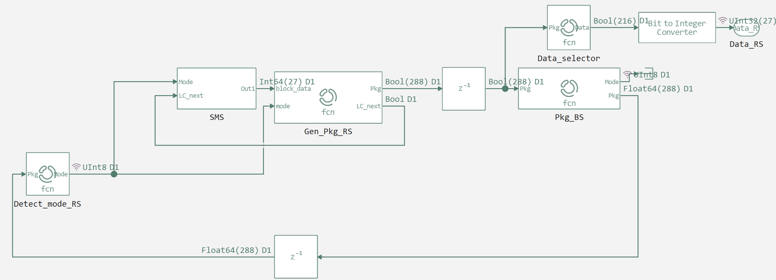
Let's move on to the description of the implemented model of interaction between the base station (BS) and the radio station (RS) in the DMR standard. The model is based on the feedback principle and includes several key blocks that ensure connection establishment, data transmission, and system status management.
The central control element of the model is the Detect_mode_RS block. It implements a finite state machine that controls the state of the radio station. The block monitors two global states: :disconnected (not connected) and :connected (connected).
The logic of the work is as follows:
- If the PC is in a state of
:disconnected, it initiates the connection by returning the value2, which corresponds to the connection request. - Able to
:connectedthe block analyzes the input data. If data is available (any(in1 .!= 0) failure counter (fail_counter) is being reset. If there is no data, the counter is incremented. - When the failure counter reaches a threshold value (for example, 3 consecutive failed frames), the radio station returns to the state
:disconnectedand initiates reconnection. - If the data is available and the connection is stable, the block returns
1to allow data transfer or0to transfer an empty frame.
This unit provides basic communication stability by simulating the behavior of a real radio station in conditions of interference or signal loss.
Next comes the text data supply unit (SMS), this unit is activated provided that the operating mode is not official (not 0 and not 2) and the next frame is not a service control frame (LC). For testing purposes, the size of the text block is set to 27 bytes. It is important to note that some of this data will later be overwritten when forming the SLOT PDU.
The Gen_Pkg_RS block is responsible for generating outgoing packets from the radio station. His work includes several stages:
- LC Header Generation (Link Control): Based on the input parameters (such as AFLCO, BFID, the address of the sender of the AdrP and the recipient of the AdrI), the structure of the control information is formed. Then a CRC is added to it for error control.
- Noise-resistant coding: LC data goes through several stages of encoding, including checksum calculation (CS5bit) and application of matrix Hemming coding (HemR, HemC).
- SLOT PDU formation: Using the function
typegenA 20-bit slot type field is generated, which includes a color code (CC) and a data type. This field is protected by the Golley code. - Packing data into a frame: Depending on the operating mode (
Mode), either a connection request is placed in the frame ([0,0,1,0]), or user data ([0,0,0,1]). The data is packed into a DMR frame structure that includes a SYNC sequence and information bits.
The unit also controls the interleaving of transmitted frames (LC and data), ensuring correct interaction with the base station.
Next comes the Pkg_BS block, which simulates the simplified behavior of the base station. His main task is to respond to requests from the radio station. This block provides the minimal feedback necessary for the model to function.
- When receiving a connection request (
[0,0,1,0]) it returns a frame with the slot type indicating the connection confirmation. - When receiving a data frame (
[0,0,0,1]) it returns a frame with confirmation of data reception. - In all other cases, an empty frame is returned.
In parallel with the Pkg_BS block, the Data_selector block operates, which is responsible for extracting useful data from the received frame (216 bits), including the SLOT PDU.
# Enabling the auxiliary model launch function.
function run_model( name_model)
    Path = (@__DIR__) * "/" * name_model * ".engee"
    if name_model in [m.name for m in engee.get_all_models()] # Checking the condition for loading a model into the kernel
        model = engee.open( name_model ) # Open the model
        model_output = engee.run( model, verbose=true ); # Launch the model
    else
        model = engee.load( Path, force=true ) # Upload a model
        model_output = engee.run( model, verbose=true ); # Launch the model
        engee.close( name_model, force=true ); # Close the model
    end
    sleep(0.1)
    return model_output
end
run_model("test_BS_RS") # Launching the model.
Mode_RS = collect(simout["test_BS_RS/Detect_mode_RS.1"]).value
Mode_BS = collect(simout["test_BS_RS/Pkg_BS.1"]).value
plot(Mode_RS, label="Mode RS", seriestype=:steppost)
plot!(Mode_BS, label="Mode BS", seriestype=:steppost)
As we can see, the system is working correctly, the PC is requesting a connection, the BS is responding, the PC is sending data, the BS is responding.
Data_out = reduce(vcat, (collect(simout["test_BS_RS/Converting bits to integers-2.1"]).value))
plot(Data_out, label="Data", seriestype=:steppost)
Analyzing the presented data graphs, we can conclude that in addition to the text symbols that were familiar to us from previous demonstrations, there are also logical channel packet (LC) data, and the peaks on the graph correspond to SLOT PDU data.
Conclusion
This model implements the basic DMR interaction cycle, including connection establishment, data transmission, and error handling. It is important to emphasize that the purpose of this development is not a detailed and complete modeling of the DMR protocol with all its specific features, but the creation of a conceptual framework and demonstration of key principles of operation. This foundation allows for further expansion of functionality.