DMR: formation of LC and A–E packets.
The Digital Mobile Radio Protocol (DMR) remains the standard for reliable professional communications. Modeling its behavior is important for testing and analysis. In the original example the basic logic of data generation and synchronization has already been laid down. However, it did not include detailed processing of the logic of transmission of control channels and packet types.
In this revised version, we have added the following points.
-
Full‑fledged logic of formation of LC packets (Logical Channel Packets).
-
Correct formation ** of packets of types A, B, C, D and E**: these are data packets that are framed by service headers, signal fields, include a sync sequence (A) or a short form LC (B,C,D,E), and also contain control bits.
-
The mechanisms of frame synchronization of the stream using xcorr have also been improved here.
This extension is suitable for full-fledged analysis of the protocol, simulation of time delays and testing on real hardware.
We will begin the implementation of this project by analyzing the written packet generation function and testing this function in scripts for its subsequent transfer to the model using the Engee function block.
First, we'll connect a file with auxiliary functions. Each function performs a specific task within the framework of data processing related to encoding, error checking, or message structure formation. Below is a list of functions with a brief description of their purpose.
-
de2bi(x, n)
Converts decimal numbersxto a binary array of lengthn(low-order bits on the right). -
bi2de(bits)
Converts a binary arraybitsto a decimal number (interpreting it as a bit string). -
encode(msg)
Calculates the control bits (CRC) for the messagemsgusing a polynomialPOLYand the Reed-Solomon coding algorithm. -
lc_header_mask(parity)
Applies a maskSTART_MASKto the parity bitsparityusing the XOR operation. -
log_mult(a, b)
Performs multiplication in the Galois field (GF(256)) using logarithmic tablesLOG_TABLEandEXP_TABLE. -
CS5bit(LCcrc)
Calculates a 5-bit checksum for a 72-bit block of dataLCcrc(sums the bytes and takes the remainder of the division by 31). -
HemR(l)
Calculates horizontal (row-by-row) Hamming verification bits for a matrixlthe size is 9x11. -
HemC(l, HR)
Calculates vertical (column-wise) Hamming verification bits for a matrixltaking into account horizontal checksHR. -
typegen(CC)
Generates a 20-bit message type based on a 4-bit codeCCadding a checksum from the tableENCODE_2087.
path = "$(@__DIR__)/dmr_lib.jl"
println("Path to the library: $path")
include(path)
The following is the function we implemented Gen_Pkg processes input parameters, generates and returns data for transmission in the form of bit sequences, controlling their sending, and
generates data frames for transmission in the communication system. The following are the main stages of the function.
-
Formation of service fields (FLCO, FID);
-
Address processing;
-
Encoding and checksums;
-
Data preparation for noise-resistant coding;
-
Formation of transmission frames;
-
Transmission sequence control;
-
Return of the finished data packet or LC block.
# Initializing global variables for status tracking
global E = 0       # Frame Counter
global l_block = 0  # Current data block

function Gen_Pkg(block, AFLCO, BFID, Switch, AdrP, AdrI, Ecstro, Shiroko, OVCM, Pr, ELC, CC)
    global E, l_block

    # 1. Formation of the FLCO (Functional Logical Channel Organization)
    FLCO = get(Dict(
        1 => [0,0,0,0,0,0],  # Type 1
        2 => [0,0,0,0,1,1],  # Type 2
        3 => [0,0,0,1,0,0],  # Type 3
        4 => [0,0,0,1,0,1],  # Type 4
        5 => [0,0,0,1,1,0],  # Type 5
        6 => [0,0,0,1,1,1],  # Type 6
        7 => [0,0,1,0,0,0]   # Type 7
    ), AFLCO, zeros(Int,6))  # The default value is zeros.

    # 2. FID (Feature ID) generation depending on the Switch
    FID = Switch == 0 ? get(Dict(
        1 => [0,0,0,0,0,0,0,0],  # Profile 1
        2 => [0,0,0,0,0,1,0,0],  # Profile 2
        3 => [0,1,1,1,1,1,1,1]   # Profile 3
    ), BFID, zeros(Int,8)) : zeros(Int,8)  # If Switch=1 - zeros

    # 3. Converting addresses to bit vectors
    AdrP_vec = (AdrP == 0) ? de2bi(1, 24) : de2bi(AdrP, 24)  # Recipient's address
    AdrI_vec = (AdrI == 0) ? de2bi(1234, 24) : de2bi(AdrI, 24)  # Source address

    # 4. Formation of a complete LC block (72 bits)
    FullLC = vcat([0, 0], FLCO, FID, [Ecstro], [0, 0, 0], [Shiroko], [OVCM],
                  de2bi(Pr - 1, 2), AdrP_vec, AdrI_vec)

    # 5. Encoding and checksum calculation
    FullLCdec = [bi2de(FullLC[i:i+7]) for i in 1:8:72]  # Byte breakdown
    parity = encode(FullLCdec)  # Reed-Solomon coding
    CRC = lc_header_mask(parity)  # Applying a mask to a checksum
    LCcrcDec = vcat(FullLCdec[1:9], CRC)  # Combining data and CRC
    LCcrc = vcat([reverse(digits(b, base=2, pad=8)) for b in LCcrcDec]...)  # In bits

    # 6. Preparation of data for BPTC (Block Product Turbo Code)
    R = [0, 0, 0, 0]  # Backup bits
    I = vcat(reverse(R[1:3]), LCcrc)  # Formation of the information block
    l = reshape(I[1:99], 11, 9)'  # Матрица 9x11
    CS = CS5bit(LCcrc)  # 5-bit checksum
    HR = HemR(l)  # Horizontal Hamming Checks
    HC = HemC(l, HR)  # Vertical Hamming Checks
    type20bit = typegen(CC)  # Generating a 20-bit message type

    # 7. Frame transfer management
    E = E == 0 ? ELC * 12 + 1 : E + 1  # Updating the frame counter

    Enabled = mod(E, 2) == 0 ? 1 : 0  # Transmission activity flag
    LCs = 0  # LC block flag
    LC_next = false  # Flag of the next LC block

    # Transmission control logic
    if E == ELC * 12 + 1
        LC_next = true
    elseif E == ELC * 12 + 2
        Enabled = 0
        LCs = 1
    elseif E == ELC * 12 + 3
        E = 1
        Enabled = 0
    end

    # 8. LC block formation (288 bits)
    LC_block = zeros(Int, 288)
    LC_block[121:168] = [1,1,0,1,0,1,0,1,1,1,0,1,0,1,1,1,1,1,1,1,0,1,1,1,0,1,1,1,1,1,1,1,1,1,0,1,0,1,1,1,0,1,0,1,0,1,1,1]  # Synchro sequence
    LC_block[111:120] = type20bit[1:10]  # The first 10 bits of the type
    LC_block[169:178] = type20bit[11:20]  # The last 10 bits of the type

    # 9. Formation of the BPTC matrix (13x15)
    BPTC = zeros(Int, 13, 15)
    BPTC[1:9, 1:11] .= l  # Basic data
    BPTC[10:13, 1:15] .= HC  # Vertical checks
    BPTC[1:9, 12:15] .= HR  # Horizontal checks
    BPTCl = vec(permutedims(BPTC))  # Conversion to vector

    # 10. Data interleaving
    LCper = zeros(Int, 195)
    for i in 1:195
        idx = mod(i * 181, 196)
        idx == 0 && (idx = 196)
        LCper[idx] = BPTCl[i]  # The interleaving algorithm
    end

    # 11. Filling in the LC block
    LC_block[14:110] .= LCper[1:97]  # The first part of the data
    LC_block[179:276] .= LCper[98:195]  # The second part of the data
    LC_block[13] = 0  # The backup bit

    # 12. Generating fast data
    FullLC = LCcrc[1:72]
    CC = reverse([1, 0, 0, 0])  # Correction code
    QR = [1, 0, 0, 0, 1, 0, 1, 1, 1]  # Quick Data
    Pi = 0  # The PI flag
    QR_rev = reverse(QR[1:8])  # Reverse fast data

    # 13. BPTC generation for fast data (8x16)
    BPTC = zeros(Int, 8, 16)
    BPTC[1:2, 1:11] = reshape(reverse(FullLC[51:72]), 2, 11)  # Part of the data
    BPTC[3:7, 1:10] = reshape(reverse(FullLC[1:50]), 5, 10)  # Basic data
    BPTC[1:7, 12:16] = [1 0 1 1 1; 0 0 0 0 0; 0 1 0 0 0; 0 0 0 0 0; 1 1 1 1 0; 0 0 0 0 0; 0 0 0 0 1]  # Control bits
    BPTC[8, :] = [0, 1, 0, 1, 0, 1, 0, 1, 0, 1, 0, 1, 0, 1, 0, 1]  # Alternating bits
    BPTC[3:7, 11] = CS  # Checksum

    # 14. Forming a bit block from the input data
    bit_block = zeros(Int, 288)
    for i in 1:27
        bits = reverse(digits(block[i], base=2, pad=8))  # Bytes to bits
        if i < 14
            bit_block[(1:8) .+ ((i-1)*8) .+ 12] = bits  # The first 13 bytes
        elseif i == 14
            bit_block[117:120] = bits[1:4]  # A special case for the 14th byte
            bit_block[169:172] = bits[5:8]
        else
            bit_block[(1:8) .+ ((i-1)*8) .+ 12 .+ 48] = bits  # The remaining bytes
        end
    end

    # 15. Formation of data frames
    DataFrames = [
        # Synchro frame
        vcat(zeros(120), [0,1,1,1,0,1,0,1,1,0,0,1,0,0,0,1,1,0,1,1,1,0,1,1,0,1,0,1,0,0,1,1,0,0,0,0,1,0,1,0,0,1,1,1,1,1,0,0], zeros(120)),
        # Data frames 1-4
        vcat(zeros(120), CC, [Pi], [0,1], [QR[9]], vec(BPTC[:, 1:4]), QR_rev, zeros(120)),
        vcat(zeros(120), CC, [Pi], [1,1], [QR[9]], vec(BPTC[:, 5:8]), QR_rev, zeros(120)),
        vcat(zeros(120), CC, [Pi], [1,1], [QR[9]], vec(BPTC[:, 9:12]), QR_rev, zeros(120)),
        vcat(zeros(120), CC, [Pi], [1,0], [QR[9]], vec(BPTC[:, 13:16]), QR_rev, zeros(120))
    ]

    # 16. Formation of the final package
    package = zeros(Int, 288)
    if Enabled == 1
        l_block += 1
        package = copy(DataFrames[l_block])
        package[13:120] .= bit_block[13:120]  # The data of the first part
        package[169:276] .= bit_block[169:276]  # The data of the second part
        if l_block == 5
            l_block = 0  # Resetting the block counter
        end
    end

    # Returning an LC block or data packet and the LC_next flag
    return LCs == 1 ? copy(LC_block) : package, LC_next
end
Next, we will test the described function. The test consists of three main parts.
-
Data preparation:
-
A test array of 2670 bytes (equal to 1) is being created
-
The input array is added in zero bytes to a multiple of 27 (block size)
-
-
Partitioning and processing:
-
Divides the data into blocks of 27 bytes.
-
Calls the function for each block
Gen_Pkg(), which forms a data frame, thereby we essentially check the operation of our function under simulation conditions.
-
-
Analysis of results:
-
Collects all generated bit blocks
-
Calculates the sum of the bits in each block (for verification)
-
Filters and outputs only non-zero amounts (we discard every second frame)
-
bytes = Int.(ones(2670))
remainder = length(bytes) % 27
bytes = vcat(bytes, remainder == 0 ? Int[] : zeros(Int, 27 - remainder))
bit_blocks = Vector{Vector{Int}}()
buffer = Int[]
pending_block = nothing
i = 1
while i <= length(bytes)
block = bytes[i:min(i+26, length(bytes))]
data_bits, LC_next = Gen_Pkg(block, 1, 1, 0, 0, 0, 0, 0, 0, 1, 2, [0, 0, 0, 1])
push!(bit_blocks, data_bits)
i += 27
end
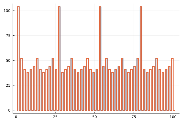
sum_bit = sum.(bit_blocks)
filtered_vector = filter(x -> x != 0, sum_bit)
println(filtered_vector)
Now let's check whether the LC packet occurs with the correct frequency. Based on the ELC = 2 setting, we will see it every 2 superframes, that is, every thirteenth frame should be 104.
indices = ((findall(x -> x == 104, filtered_vector)).-1)/13
Now let's delete LC and check if the rest of the frames are alternating.
# Delete all 104(LC)
filtered_vector = filter(x -> x != 104, filtered_vector)
# The desired combination
pattern = [52, 41, 38, 41, 44] # A, B, C, D, E

function check_pattern(vec, pat)
    # Crop the vector to the nearest suitable length
    pattern_length = length(pat)
    suitable_length = div(length(vec), pattern_length) * pattern_length
    trimmed_vec = vec[1:suitable_length]
    # Checking the pattern match
    for i in 1:pattern_length:length(trimmed_vec)
        if trimmed_vec[i:i+pattern_length-1] != pat
            return false
        end
    end
    return true
end

# Checking the filtered_vector
is_correct = check_pattern(filtered_vector, pattern)
println("Is the $pattern combination repeated? ", is_correct ? "Yes" : "No")
As we have seen, the function is working correctly. Now let's test the models.
Let's run the model for which we have created a binding for our function.
# Enabling the auxiliary model launch function.
function run_model( name_model)
    Path = (@__DIR__) * "/" * name_model * ".engee"
    if name_model in [m.name for m in engee.get_all_models()] # Checking the condition for loading a model into the kernel
        model = engee.open( name_model ) # Open the model
        model_output = engee.run( model, verbose=true ); # Launch the model
    else
        model = engee.load( Path, force=true ) # Upload a model
        model_output = engee.run( model, verbose=true ); # Launch the model
        engee.close( name_model, force=true ); # Close the model
    end
    sleep(0.1)
    return model_output
end
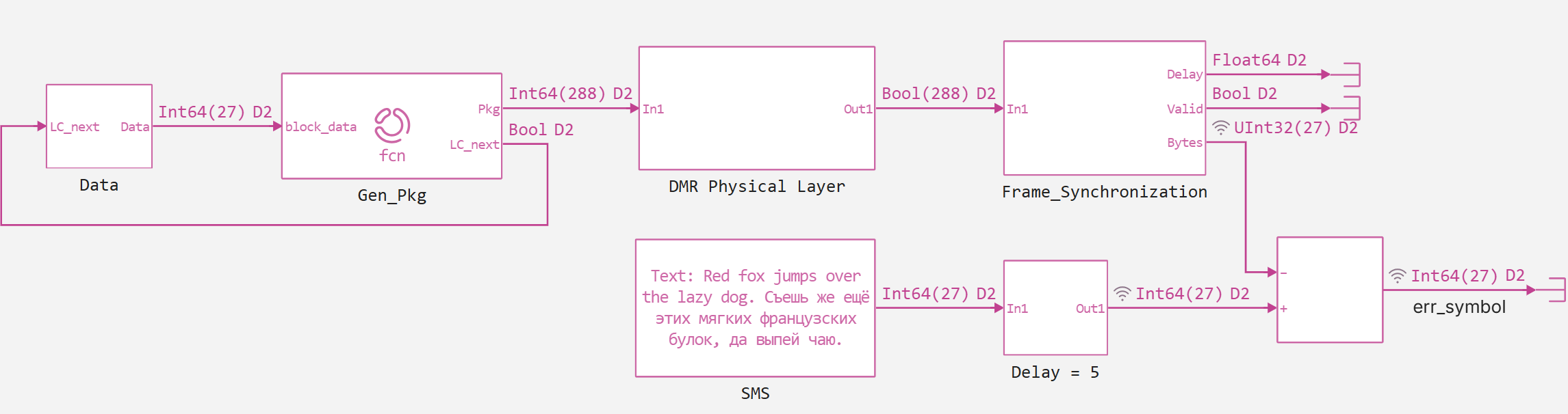
Based on the graphs below, we see that, firstly, the LC_next control signal warns us that the next frame is working correctly, and secondly, we see that the function behaves identically in the model and in the script. Plus, for the convenience of defining package parameters in the Engee Function, we use parameter declaration, thereby reducing the number of input ports of the block..png)
display(run_model("test_new_function"))
gr()
display(plot(vcat(collect(simout["test_new_function/Switch.1"]).value...)))
plot(sum_bit, seriestype = :steppre, linewidth=3, legend = false)
plot!(vcat(collect(simout["test_new_function/Sum of elements.1"]).value...), seriestype = :steppre, linewidth=3, legend = false)
.png)
Now that we have tested the function itself, we can proceed to improving our DMR system model.
.png)
As we can see from the screenshot above, the block Gen_Pkg controls the data input, inside the block DMR Physical Layer the logic described in the previous version of this example is located, and in the block Frame_Synchronization There are two functions that perform the frame synchronization of our stream. Let's look at these blocks, let's start with Xcorr.
# Глобальная переменная для хранения задержки
global Delay = 0

# Основная функция обработки блока данных
function (c::Block)(t::Real, BitSignal)
    global Delay
    US = false  # Флаг успешной синхронизации

    # Эталонная синхропоследовательность (48 бит)
    Data_Sync = [-1, 1, 1, 1, -1, 1, -1, 1, 1, -1, -1, 1, -1, -1, -1, 1,
                 1, -1, 1, 1, 1, -1, 1, 1, -1, 1, -1, 1, -1, -1, 1, 1,
                 -1, -1, -1, -1, 1, -1, 1, -1, -1, 1, 1, 1, 1, 1, -1, -1]

    # Вычисление взаимной корреляции между входным сигналом и синхропоследовательностью
    MS = xcorr_simple((2*BitSignal.-1), Data_Sync)

    # Поиск пиков корреляции (порог > 46)
    Peak = findall(MS .> 46)

    if !isempty(Peak)
        P = Peak[1]  # Берем первый значимый пик

        # Проверяем, находится ли пик в допустимом диапазоне
        if P > 120 && P < 456
            # Вычисляем задержку в зависимости от положения пика
            if P > 288
                Delay = P-408
            else
                Delay = P-120
            end
        end
        US = true  # Устанавливаем флаг успешной синхронизации
    end

    D = Delay  # Текущее значение задержки
    return US, D, MS  # Возвращаем статус синхронизации, задержку и массив корреляции
end
Now let's move on to the block Selector.
# Глобальные переменные для управления состоянием обработки:
global U = false  # Флаг активности обработки сигнала
global j = 0      # Счетчик временных интервалов

# Основная функция обработки блока данных
function (c::Block)(t::Real, BitSignal, US, Delay)
    global U, j  # Доступ к глобальным переменным

    # Инициализация выходного сигнала (216 бит)
    Sig = zeros(216)

    # Флаг разрешения обработки
    Enable = false

    # Обработка сигнала синхронизации (US):
    # Если получен сигнал синхронизации (US != 0), сбрасываем состояние
    US != 0 ? (U = US; j = 0) : nothing

    # Если обработка активна (U == 1)
    if U == 1
        j += 1  # Увеличиваем счетчик

        # Обрабатываем только нечетные интервалы
        if isodd(j)
            # Формируем выходной сигнал, выбирая биты из BitSignal с учетом задержки:
            # - Блок 1: биты 13-120 (108 бит)
            # - Блок 2: биты 169-276 (108 бит)
            # Общая длина: 216 бит
            Sig .= BitSignal[Int.([collect(13:120); collect(169:276)] .+ Delay)]
            Enable = true  # Активируем флаг разрешения
        end
    end

    # Сброс состояния после 12 интервалов
    j == 12 ? (U = false; j = 0) : nothing

    # Возвращаем:
    # - Enable: флаг наличия валидных данных
    # - Sig: обработанный сигнал (216 бит)
    return Enable, Sig
end
Now let's run the model and check its correctness by calculating the number of errors at the output relative to the input.
More interesting tests are presented in the first version of the model. If you wish, you can apply them to this model as well, but we decided not to do so here, so as not to artificially increase the volume of the material being analyzed in this example.
display(run_model("DMR_V2"))
println("The total number of errors in bytes is: ",sum(vcat(collect(simout["DMR_V2/err_symbol"]).value...)))
Output
In this example, a fairly significant part of the DMR protocol was analyzed. Next time, if you are interested in this topic, we will analyze the MAC layer, namely the logic of responses to channel frames and control frames.