A model of a single-position radar system using system objects
This model demonstrates the operation of a simple single-position radar system.
Description of the system model
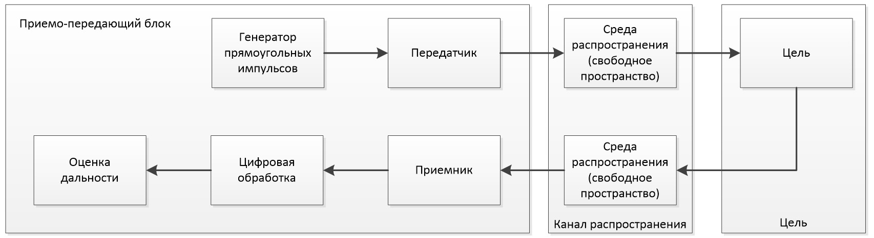
The special feature of the model is that the radar transmitter and receiver do not contain an antenna array, so the antenna is equivalent to a simple isotropic element.
A sequence of rectangular pulses is used as a probing signal, which are amplified in the transmitter.
Then, from the output of the transmitter, the signal propagates to the target through the free space. The reflected signal is sent to the receiver.
The receiver amplifies the signal and also adds its own noise.
A matched filter is used as the processing unit, propagation losses are compensated by gain control.
The final stage of processing is incoherent accumulation. The scheme of the model is shown in the figure
Digital processing consists of the following elements:
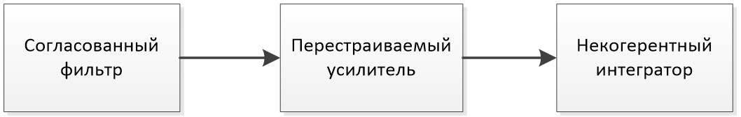
Implementation of the blocks described above.
Validation of input parameters
cd( @__DIR__ )
using Pkg; Pkg.add("DSP")
include( "initRadarParam.jl" );
paramRadar = initRadarParam();
Definition of a rectangular signal.
rectangular = EngeePhased.RectangularWaveform(
    SampleRate = paramRadar.fs, # Character rate
    DurationSpecification = "Pulse width", # Method
    PulseWidth = 1/paramRadar.pulseBw, # Pulse width
    PRF = paramRadar.prf,
    FrequencyOffset = 0, # Frequency offset
    OutputFormat = "Pulses", # Output format
    NumPulses = 1, # Number of pulses
    PRFOutputPort = false, # PRF output port
    CoefficientsOutputPort = false
); # Coefficient output port
Determining the parameters of the transmitter.
transmitter = EngeePhased.Transmitter(
    PeakPower = paramRadar.peakPower, # Peak power
    Gain = paramRadar.txGain, # Gain factor
    LossFactor = paramRadar.lossFactor, # Loss ratio
    InUseOutputPort = true, # The output port is being used
    CoherentOnTransmit = true); # Coherent in transmission
Definition of the external channel.
free_space_1 = EngeePhased.FreeSpace(
    SampleRate = paramRadar.fs, # Sampling rate
    PropagationSpeed = paramRadar.propSpeed, # The speed of propagation
    OperatingFrequency = paramRadar.fc, # Operating frequency
    TwoWayPropagation = false, # Two-way distribution
    MaximumDistance = paramRadar.maxRange # Maximum distance
);
free_space_2 = EngeePhased.FreeSpace(
    SampleRate = paramRadar.fs,
    PropagationSpeed = paramRadar.propSpeed,
    OperatingFrequency = paramRadar.fc,
    TwoWayPropagation = false,
    MaximumDistance = paramRadar.maxRange
);
Setting up the radar.
target = EngeePhased.RadarTarget(
    MeanRCS = paramRadar.target1Rcs, # Average RCS value
    Model = "Nonfluctuating", # Model
    PropagationSpeed = paramRadar.propSpeed, # The speed of propagation
    OperatingFrequency = paramRadar.fc); # Operating frequency
Enabling noise in the channel, if noise is not equal to 1, then there is no noise in the channel.
noise = 1; # On/Off Noise

noise == 1 ?  print("A receiver with noise")  :  print("The receiver is noise-free")
receiver = EngeePhased.ReceiverPreamp(
    Gain = paramRadar.gain, # Growth
    LossFactor = paramRadar.lossFactor, # Loss ratio
    NoiseMethod = "Noise temperature", # The noise method
    NoiseFigure = 0.2, # Noise factor
    ReferenceTemperature = noise == 1 ? paramRadar.referenceTemperature : 1e-323, # Reference temperature
    SampleRate = paramRadar.fs, # Sampling rate
    EnableInputPort = true, # Control input port
    PhaseNoiseInputPort = false) # Phase noise input port
Filter Definition
mfilter = EngeePhased.MatchedFilter(
    CoefficientsSource="Property",
    Coefficients = paramRadar.matchingCoeff, # Coefficients
    SpectrumWindow = "None", # The Spectrum window
    GainOutputPort = false # Gain output port
);
Determination of the gain change over time.
TVG = EngeePhased.TimeVaryingGain(
    RangeLoss = paramRadar.rangeLoss, # Loss of range
    ReferenceLoss = paramRadar.referenceLoss # Reference losses
);
Definition of the pulse integrator.
integrator = EngeePhased.PulseIntegrator(
    CoherentFlag = "Noncoherent", # Method
    NumberPulses = paramRadar.numPulseInt, # Number of pulses
    IntegrationOverlap = 0
);
Definition of a moving platform.
platform = EngeePhased.Platform(
    MotionModel = "Velocity", # Movement model
    InitialPosition = paramRadar.target1Pos, # Starting position
    Velocity = paramRadar.target1Vel, # Speed
); # 1/paramRadar.prf
Performing processing in a loop. All the objects described above are combined into one system and executed in a loop describing the operation of the system over time.
N = paramRadar.numPulseInt

for i = 0:9
    rectangular_out = rectangular()
    platform_pos, platform_vel = platform(1/paramRadar.prf)
    transmitter_out, transmitter_status = transmitter(rectangular_out)
    free_space_1_out = free_space_1(transmitter_out, paramRadar.radar_pos, platform_pos, paramRadar.radar_vel, platform_vel)
    target_out = target(free_space_1_out)
    free_space_2_out = free_space_2(target_out, platform_pos, paramRadar.radar_pos,platform_vel, paramRadar.radar_vel)
    receiver_out = receiver(free_space_2_out, [~transmitter_status[i] for i ∈ eachindex(transmitter_status)])
    filter_out = mfilter(receiver_out)
    TVG_out = TVG(filter_out)
    global integrator_out = integrator(TVG_out)
end
Displays of the integrator output in the range from 0 to 5000 m
plot(paramRadar.rangeGates, abs.(integrator_out)*1e6,label="",
    xlabel="Range, m", ylabel="Power, MCW",
    title="The response of the reflected signal after consistent filtering ",
    titlefont=font(14,"Computer Modern"),fontfamily="Compute Modern",lw=2,gridalpha=0.2)
Conclusion
We have reviewed the operation of a simple single-position radar system. The final graph of the integrator's output shows that the system has found a peak, that is, it was able to detect an object at a distance of 2000 meters. This means that this radar method is working correctly.