The model of operation of the drive with a DC motor
In this article, we will consider a drive model based on a DC motor. A special feature of this example is the use of basic blocks and blocks of physical modeling.
The composition of the model
Model ee_dc_motor_ctl It consists of a number of subsystems.
- The speed control subsystem Controller is made using basic blocks. This makes it easy to set the control algorithm.;
- The control object is a DC motor DC Motor. It is presented in the form of blocks of physical modeling of the "Electricity" library;
- The Driver subsystem is used to set the engine speed.;
- To determine the speed of the motor shaft, a sensor is needed, which is implemented in the Sensor subsystem.
Subsystem of the speed controller
The Controller subsystem implements a PI controller with a low-pass filter. The regulator circuit is shown below.
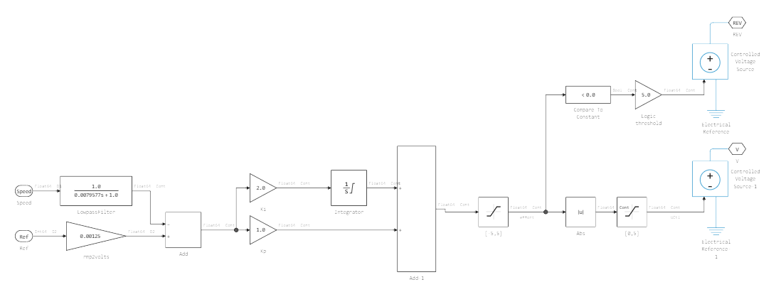
The operating principle of the controller is simple. The input of the controller receives the desired speed value and the value of the current rotation speed of the motor shaft. However, the motor is controlled via voltage, so all speeds should be converted. In the diagram, this is implemented as a multiplication by a factor of 0.00125. In the next step, the misalignment is calculated in the Add block. After that, an adjusted value is generated, which will be applied to the driver input. Since the driver is implemented as physical blocks, a voltage source Controlled Voltage Source is used to generate the output voltage.
Engine driver subsystem
The Driver subsystem is a model of the driver circuit in the form of physical blocks. The Controlled PWM Voltage unit generates a PWM signal based on the voltages at its ref+ and ref- ports. The H-Bridge block is an H-bridge circuit that makes it possible to reverse the polarity of the applied voltage.
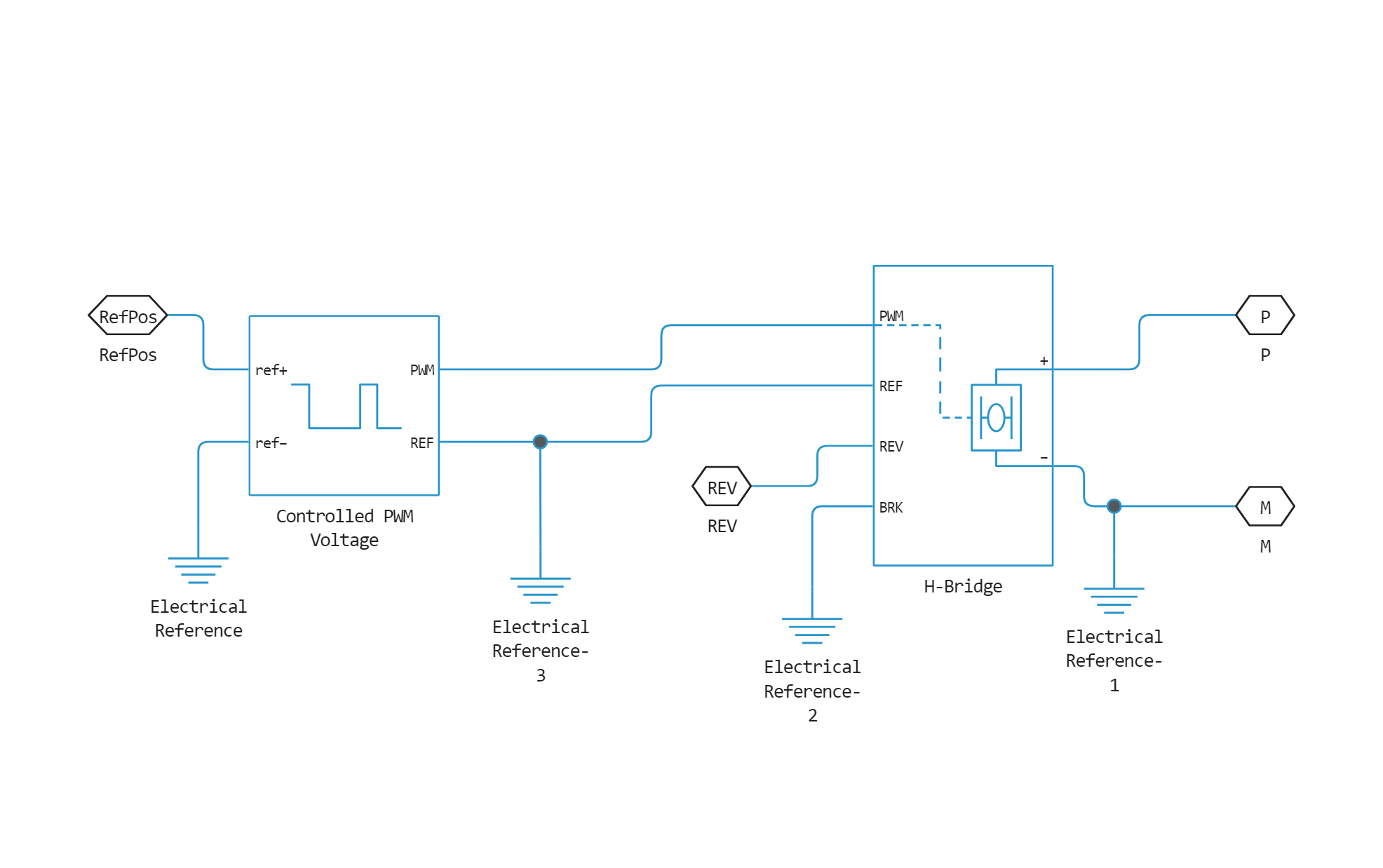
The voltage generated at the output of the driver goes to the input of the motor. For more information about the block parameters, see the documentation in the section DC Motor.
Sensor subsystem
The Sensor subsystem contains the base units and the Ideal Rotary Motion Sensor physical unit. This unit allows you to determine the engine shaft speed.
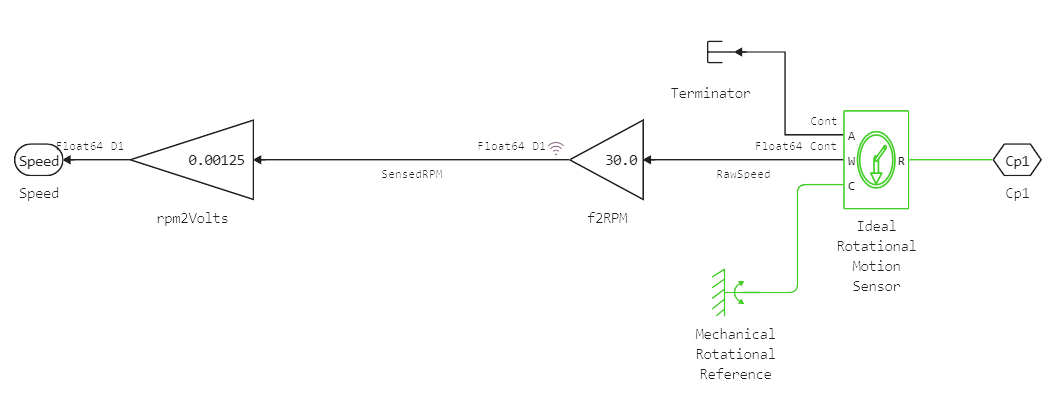
After reading the speed, it is necessary to convert its value to volts for further regulation in the Controller unit.
Getting system data
Let's run the model and see how the controller fulfills the set speed in this model.
# Enabling the auxiliary model launch function.
function run_model( name_model, path_to_folder )

    Path = path_to_folder * "/" * name_model * ".engee"

    if name_model in [m.name for m in engee.get_all_models()] # Checking the condition for loading a model into the kernel
        model = engee.open( name_model ) # Open the model
        model_output = engee.run( model, verbose=true ); # Launch the model
    else
        model = engee.load( Path, force=true ) # Upload a model
        model_output = engee.run( model, verbose=true ); # Launch the model
        engee.close( name_model, force=true ); # Close the model
    end

    return model_output
end
run_model("ee_dc_motor_ctl",@__DIR__) # Launching the model.
# Reading of encoded signals from simout
Wref = simout["ee_dc_motor_ctl/Wref"];
Wref = collect(Wref);

SensedRPM = simout["ee_dc_motor_ctl/Sensor/SensedRPM"];
SensedRPM = collect(SensedRPM);
Let's plot the given speed and the speed obtained from the sensor.
using Plots

plot(Wref.time, Wref.value, label = "Wref")
plot!(SensedRPM.time, SensedRPM.value, label = "SensedRPM")
Conclusion
According to the graphs, it can be concluded that the speed of the motor shaft reached the set speed in 3 seconds. The time to achieve the desired result can be reduced by changing the components of the PI controller.