Design and modeling of a binary frequency manipulation system
This article discusses the process of developing and modeling a data transmission system using Binary Frequency Shift Keying (BFSK)**. FSK modulation is a fundamental concept in modern communication systems. In its binary version, the logical "0" and "1" correspond to two different harmonic signals with frequencies ( f_1 ) and ( f_2 ). BFSK is widely used in low-speed applications due to its noise immunity and ease of implementation, for example, in Bluetooth, GSM technologies in the early stages, as well as in various telemetry and radio control systems.
In this article, we will develop a model of a communication system with BFSK, we will go through the following stages:
- Generation of the original digital signal.
- BFSK modulation: Signal generation by selecting one of two carrier frequencies depending on the bit.
- BFSK demodulation: implementation of an incoherent detection method. It is based on dividing the signal into two frequency channels using bandpass filters, separating their envelopes, and deciding in favor of the channel where the amplitude of the envelope is greater.
- Analysis of results: Comparison of the transmitted and received messages.
A special feature of our work is the use of a cascade of Biquad filters ** (Biquad Filter)** in the demodulator. In order to correctly isolate the information components of the BFSK signal, it is necessary to make sure that the filters are tuned exactly to the frequencies used in the modulator. To this end, we performed an analysis of their amplitude-frequency (AFC) and phase-frequency (FCH) characteristics.
using JLD2, Plots
SOS = load("filter_matrix.jld2", "SOS")
Scale = load("filter_matrix.jld2", "Scale")
println("Size SOS: $(size(SOS))")
println("Size Scale: $(size(Scale))")
The filter coefficients have been pre-calculated and saved to a file. filter_matrix.jld2. Two key variables are loaded:
- SOS (Second-Order Sections) is a matrix of coefficients for each biquadrate link. Matrix size
(15, 6)This means that the filter consists of 15 sequentially connected biquadrate links, each of which is described by six coefficients. - Scale is a vector of scaling coefficients for each link. Size
(16, 1)indicates that in addition to the 15 links, an additional scaling factor has been added.
Such a structure (a cascade of biquadrate links) is a standard way to implement high-order filters that provide numerical stability.
Frequency response calculation function
This function implements the calculation of the complex transmission coefficient of the cascade filter.:
-
For each frequency from the specified range, the normalized angular frequency is calculated
omega -
A complex variable
z = exp(1im * omega)corresponds to a point on the unit circle in the Z-plane -
For each link , its transfer function is calculated in the form:
-
The total transmission coefficient is obtained by multiplying the transfer functions of all links and the final scaling factor
function biquad_freq_response(SOS, Scale, freqs, fs)
    n_sections = size(SOS, 1)
    n_freqs = length(freqs)
    H = ones(ComplexF64, n_freqs)

    for i in 1:n_sections
        b0, b1, b2, a0, a1, a2 = SOS[i, :]
        for j in 1:n_freqs
            omega = 2π * freqs[j] / fs
            z = exp(1im * omega)
            H_section = (b0 + b1/z + b2/z^2) / (a0 + a1/z + a2/z^2)
            H[j] *= H_section
        end
    end
    H .*= prod(Scale)
    return H
end
The calculation is performed for frequencies from 0 to 24 MHz (half the sampling frequency of 48 MHz) with a resolution of 1024 points.
Scale_vec = vec(Scale)
fs = 48000000
n_freqs = 1024
freqs = range(0, fs/2, length=n_freqs)

H = biquad_freq_response(SOS, Scale_vec, freqs, fs)
magnitude = 20*log10.(abs.(H))
phase = rad2deg.(angle.(H))
display(plot(freqs, magnitude, xlabel="Frequency (Hz)", ylabel="Amplitude (dB)", title="Filter frequency response"))
display(plot(freqs, phase, xlabel="Frequency (Hz)", ylabel="Phase (degrees)", title="Frequency response of the filter"))
There are several conclusions that can be drawn from the graphs:
-
High out-of-band suppression: Frequency response values decrease rapidly outside the bandwidth. This indicates the excellent selectivity of the filter — signals at frequencies other than the target are suppressed almost completely.
-
Zero attenuation in the band: At the frequency response peaks, the value is close to 0 dB (about 10⁻⁸ dB), which means that the useful signal passes through practically without attenuation.
-
Phase shift nonlinearity: Complex phase behavior is observed in the passbands, which is typical for high-order filters. This will lead to some phase distortion of the signal, but for incoherent detection, where only the amplitude of the envelope is analyzed, phase distortion is not critical.
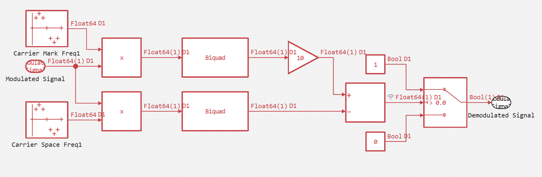
Demodulation of the BFSK signal (block FSK Demodulator), implements an incoherent detector based on bandpass filters. This method does not require precise knowledge of the carrier phase, which simplifies implementation.
The algorithm of the demodulator consists of the following steps:
- The input BFSK signal is applied in parallel to two multipliers (Product).
- The formation of two parallel channels at different frequencies:
- In the upper channel, the signal is multiplied by a reference oscillation with a frequency of "1" (
Carrier Mark Freq1). The result of the multiplication contains a low-frequency component (proportional to the cosine of the phase difference) and high-frequency harmonics.- In the lower channel, the signal is multiplied by a reference oscillation with a frequency of "0" (
Carrier Space Freq1
- In the lower channel, the signal is multiplied by a reference oscillation with a frequency of "0" (
- The signals from the outputs of the multipliers are sent to identical bandpass filters (
Biquad FilterandBiquad Filter-1). These filters play a key role.:- They suppress the high-frequency components that occur during multiplication.
- Their bandwidth is configured in such a way as to allocate exactly the frequency that corresponds to the channel. In fact, each filter works as an envelope detector. At the filter output, we receive a signal whose amplitude is proportional to the amplitude of the input signal at the filter setting frequency.
- Gain and comparison:
- Filtered signals are amplified with different Gain coefficients to compensate for losses and bring them to a range that is convenient for comparison.
- Next, the signals are sent to the subtractor.
- The resulting difference signal is applied to the control port
Switch.- If the difference is
> 0(the energy in channel "1" is greater than in channel "0"), the key passes the value "1" to the output. - Otherwise, if the difference is
< 0, a "0" is applied to the output.
- If the difference is
- The digital signal generated in this way (
Demodulated Signal) corresponds to the original transmitted sequence.
Next, run the model.
.png)
function run_model( name_model)
    Path = (@__DIR__) * "/" * name_model * ".engee"
    if name_model in [m.name for m in engee.get_all_models()]
        model = engee.open( name_model )
        model_output = engee.run( model, verbose=true );
    else
        model = engee.load( Path, force=true )
        model_output = engee.run( model, verbose=true );
        engee.close( name_model, force=true );
    end
    sleep(0.1)
    return model_output
end
run_model("Binary_FSK")
Now let's sequentially extract the simulation results.:
- Input_Signal - the original set of bits.
- Modulated_Signal - generated BFSK signal .
- filt_1_minus_filt_2 is the difference signal after the filters.
- Demodulated_Signal - The restored digital signal.
Input_Signal = (collect(simout["Binary_FSK/Signal From Workspace.1"]).value)
Input_Signal = [x for subvec in Input_Signal for x in subvec]
println("Input_Signal: $Input_Signal")
The principle of operation of the BFSK modulator is extremely simple, it functions as a controlled switch.:
- A digital signal is applied to the input of the modulator
Digital Data(a sequence of bits: 0 and 1). - The modulator contains two harmonic signal generators (Sine Wave):
Carrier Mark FreqGenerates a signal with a frequency corresponding to the logical "1" (mark frequency). In our model, this is the frequency (f_1), the period of which fits 5 times per clock cycle (Samples=5).Carrier Space FreqGenerates a signal with a frequency corresponding to the logical "0" (space frequency). In our model, this is the frequency (f_2), the period of which fits 50 times per clock cycle (Samples=50).
- Control signal
Digital DataIt is applied to the control port of the switch, and a BFSK signal is generated at the output of the modulator, ready for transmission.
.png)
Below is a graph of the modulated signal for our bit sequence.
Modulated_Signal = (collect(simout["Binary_FSK/FSK Modulator.Modulated Signal"]).value)
Modulated_Signal = [x for subvec in Modulated_Signal for x in subvec]
println("Input_Signal: $Input_Signal")
plot(Modulated_Signal)
The signal filt_1_minus_filt_2 It represents the difference between the filtered components of channels "1" and "0" in the demodulator. Its shape is determined by the following factors:
-
Switching bits causes sharp transitions between the positive and negative regions, corresponding to a change in the transmitted character.
-
The inertia of the filters (system memory) generates damped oscillations after each switch, which is explained by the finite bandwidth of the filters (as seen from the frequency response).
-
Inter-character interference occurs due to overlapping responses from previous bits, which complicates the waveform.
The main thing: For demodulation, not the entire complex waveform is used, but only its sign at the moment of gating, which allows you to unambiguously restore the original bit sequence.
filt_1_minus_filt_2 = (collect(simout["Binary_FSK/FSK Demodulator/Add.1"]).value)
filt_1_minus_filt_2 = [x for subvec in filt_1_minus_filt_2 for x in subvec]
println("Input_Signal: $Input_Signal")
plot(filt_1_minus_filt_2)
As we can see, as a result, the input set of bits was correctly decoded.
Demodulated_Signal = (collect(simout["Binary_FSK/FSK Demodulator.Demodulated Signal"]).value)
Demodulated_Signal = [x for subvec in Demodulated_Signal for x in subvec]
println("Input_Signal: $Input_Signal")
println("Demodulated_Signal: $(Demodulated_Signal[2:1100:end])")
display(plot(Demodulated_Signal))
Conclusion
As a result of the work done, a simulation model of a binary frequency manipulation (BFSK) communication system was successfully created and tested. Comparison of the transmitted ([1, 0, 0, 1, 0]) and the accepted sequence confirmed that the developed demodulation scheme correctly restores the original data in conditions of an ideal communication channel. This result confirms the operability of the proposed architecture with a cascade of biquadrate filters and the correct choice of system parameters, which is the basis for further complicating the model, for example, by adding noise to the communication channel to assess noise immunity.