QPSK communication system with adaptive alignment
The model presented in this example demonstrates a practical QPSK modulated digital communication system that combats the real problems of wireless channels: frequency offsets, multipath fading, and noise. The main goal is to show the effectiveness of adaptive channel alignment using an RLS filter to compensate for distortion.
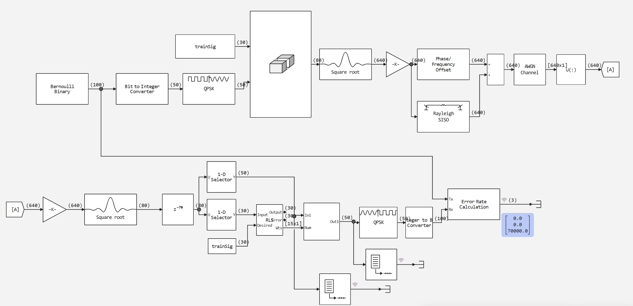
Full data transmission path:
- Generation of bits → Modulation → Pulse shaping
- Passing through a realistic communication channel
- Reception → Alignment → Demodulation → Error estimation
Key channel effects:
- Phase and frequency shift (Doppler up to 10 Hz+ fixed 120° shift)
- Multipath propagation (two paths with different delays and attenuations)
- Additive white Gaussian noise (SNR = 30 dB)
Frame structure
- Training sequence (30 characters) — used to "train" the adaptive filter
- Useful data (50 characters) — real information
- This structure simulates practical communication systems (Wi-Fi, LTE), where pilot signals are periodically transmitted.
Two-stage processing
Кадр → [Обучающая часть] → RLS-фильтр (обучение) → [Данные] → FIR-фильтр (применение весов)
- Training stage: The RLS filter adjusts coefficients based on a known training sequence
- Operation stage: The adjusted weights are used in the FIR filter to align the useful data
What the model demonstrates
-
The viability of QPSK in difficult conditions — even with frequency shifts and fades, the system remains operational
-
Adaptive equalization efficiency — how a properly tuned filter can "clean up" a distorted signal
-
A practical approach to synchronization is to use training sequences instead of ideal assumptions.
-
Compromise between efficiency and overhead — 30 characters of training per 50 characters of data (37.5% overhead)
Application areas
- Educational demonstration of the principles of digital communication
- Testing of alignment and compensation algorithms
- Evaluation of the noise immunity of various modulation schemes
- Prototyping solutions for wireless systems
Now let's move on to initializing and running the model. The code below initializes the parameters of the QPSK communication system with adaptive alignment: sets the transmission rate of 1 Mbit/s, the frame structure (100 bits, including 30 training characters), the parameters of the modulation and shaping filter, adjusts the channel with a frequency offset of up to 10 Hz and double-beam fading, and determines the parameters of the RLS filter (15 weights and a forgetting factor of 0.95) and prepares a training sequence for adjusting the equalizer.
bitRate = 1000000;
numBitsPerFrame = 100;
bitsPerSymbol = 2;
numTrainSyms = 30;
pulseDelay = 8;
oversampleFactor = 8;
rolloffFactor = 0.2;
modOrder = 2^bitsPerSymbol;
numDataSymsPerFrame = numBitsPerFrame / bitsPerSymbol;
numSymsPerFrame = numDataSymsPerFrame + numTrainSyms;

qpskmod = EngeeComms.QPSKBasebandModulator(PhaseOffset = pi/4);
trainSig = qpskmod(rand(0:modOrder-1,numTrainSyms));
maxDoppler = 10;

numEqWeights = 15;
refTap = 8;
lambda = 0.95;
snrdB = 30;


symbolPeriod = bitsPerSymbol/bitRate;
chanSamplePeriod = symbolPeriod/oversampleFactor * 50/80;

pathDelays = [0 chanSamplePeriod];
pathGains = [0 -6];

numDataSymsPerFrame = numBitsPerFrame / bitsPerSymbol;
numSymsPerFrame = numDataSymsPerFrame + numTrainSyms;

initEqWeights = complex(zeros(numEqWeights));
eqDelay = refTap - 1;
trimTrainSig = trainSig[1:end-eqDelay];

println("Speed: $(bitRate/1e6) Mbps, Frame: $(numBitsPerFrame) bits")
println("Structure: $(Int.(numDataSymsPerFrame)) data + $(numTrainSyms) training characters")
println("Channel: Doppler $(maxDoppler) Hz, 2 beams, SNR$(snrdB) dB")
println("Equalizer: RLS filter of $(numEqWeights) samples, λ=$(lambda)")
function run_model( name_model)
    Path = (@__DIR__) * "/" * name_model * ".engee"
    if name_model in [m.name for m in engee.get_all_models()] # Checking the condition for loading a model into the kernel
        model = engee.open( name_model ) # Open the model
        model_output = engee.run( model, verbose=true ); # Launch the model
    else
        model = engee.load( Path, force=true ) # Upload a model
        model_output = engee.run( model, verbose=true ); # Launch the model
        engee.close( name_model, force=true ); # Close the model
    end
    sleep(0.1)
    return model_output
end
run_model("qpsk_freqfade")
WorkspaceArrays.plot_wa(WorkspaceArray{Vector{Float64}}("qpsk_freqfade/Error Rate Calculation.Output_1"))
Output
Analyzing the BER graph, we clearly see that with our channel parameters, the error is zero. The system shows that even relatively simple adaptive filtering methods (RLS+ pilot training) can effectively combat serious distortions in real communication channels, making high-speed data transmission possible in non-ideal conditions. The model illustrates a fundamental principle of digital communications: processing on the receiving side can compensate for many of the problems of the physical channel, turning a "dirty" analog signal into pure digital data.