Code generation for STM32 (Full-step stepper motor control)
Introduction
In this demo, a hardware embodiment of the example [full-step bipolar stepper motor control] is implemented. двигателем](https://engee.com/community/ru/catalogs/projects/polnoshagovoe-upravleniia-shagovym-dvigatelem/edit).
Hardware part
The control object of this example is a bipolar stepper motor 17HS1352-P4130, as already indicated in the simulation example. The converter uses a dual full-bridge MOSFET driver L6206PD based on the expansion card X-NUCLEO-IHM04A1. This board is compatible with the STM NUCLEO F446RE microcontroller debugging board, which is described in [corresponding example] (https://engee.com/community/ru/catalogs/projects/knopka-i-svetodiod-na-stm32 ).
The diagram below shows the connection diagram of the drive.
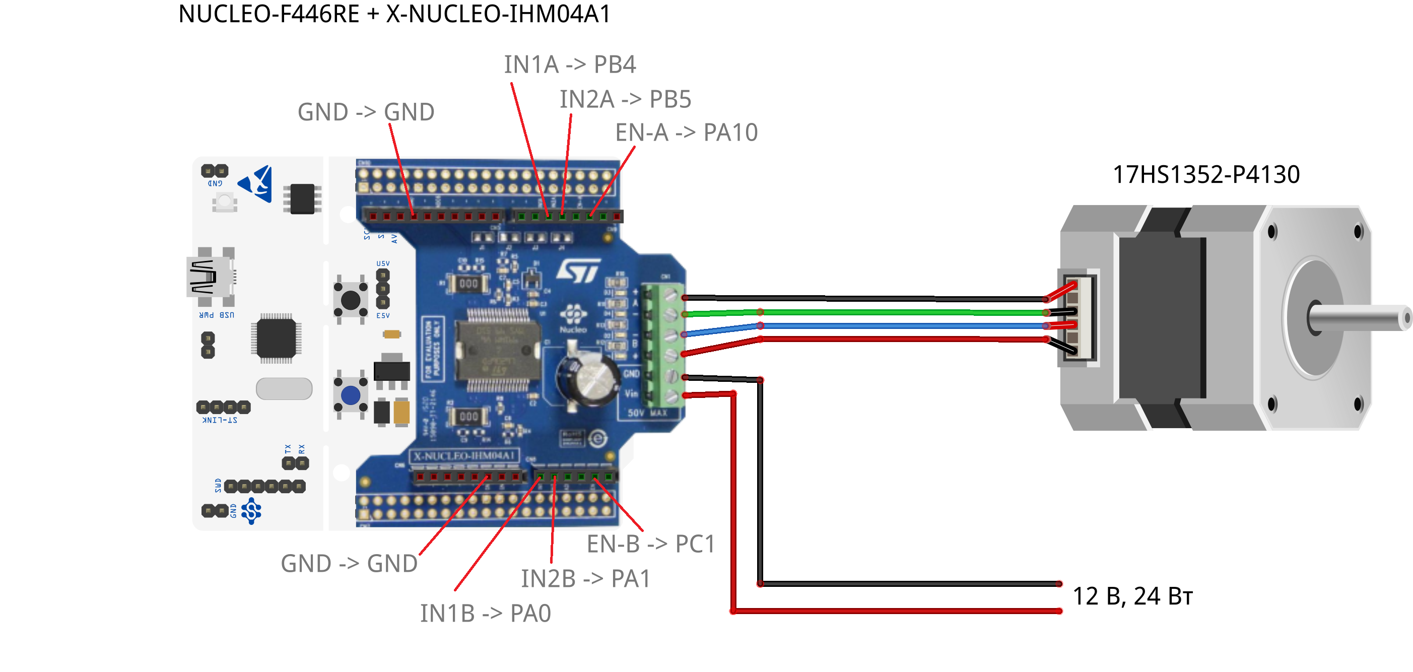
According to the pinout and schematic diagram of the IHM04A1 board, as well as the functional diagram of the driver, the EN-A and EN-B inputs are designed for hardware activation/deactivation of the A and B bridges of the driver. Inputs IN1A and IN2A control the first and second arms of bridge A, inputs IN1B and IN2B control bridge B.

The control inputs are connected to the GPIO of the debugging board, as indicated in the wiring diagram. The frequency of the signals to the control inputs, according to the motor data, is not more than 250 Hz. In view of this, it is sufficient to use peripheral digital input modules to implement the control; PWM modules will not be considered in this example.
Management system model
In comparison with the model used in the original example, the new model differs only in the blocks of the controller peripherals based on the blocks C Function and blocks for matching data types/dimensions of input signals. All of them are included in the subsystem "Control System".
.png)
Blocks C Function "BUTTON_GPIO_PC13" and "LED_GPIO_PA5" have already been shown in STM32 digital input/output example. Block C Function "NUCLEO_IHM04A1" is necessary to implement the interaction of the control algorithm with the peripherals used to control the driver - digital inputs PA10, PB4, PB5, PC1, PA0, PA1. This unit also implements exclusively full-step driver control.
When the block is applied to the input enable The high signal level is also set to GPIO PA10, PC1, which includes both driver bridges. At the entrance pulses A vector of GPIO states PB4, PB5, PA0 and PA1 is transmitted to the block, thereby enabling/disabling the corresponding driver keys.
In this block, you should also pay attention to the fact that the states of the inputs in the previous step are stored in global variables. flag and flags. These variables are declared in вкладке Shared Code the block.
A user program with an algorithm generated from the "Contol System" subsystem will work as follows: at the trailing edge of the signal, after pressing the push-button contact built into the board, the LED built into the board lights up, the driver bridges turn on, and the sequential generation of control pulses begins. The sequence of pulses for rotating the motor shaft clockwise corresponds to the output of pulses to the inputs in the order PB4-PB5-PA0-PA1. After pressing the button contact again, the driver bridges and the LED turn off, and the pulse output stops.
Simulation results
Since we have made changes to the original model, we will simulate it again, repeating the same steps of the original example So that we can verify the identity of the algorithms and verify the correctness of the work with the signals coming to the blocks. C Function.
Downloading the necessary libraries:
using Plots
using DataFrames
plotlyjs();
Launching the model:
modelName = "stm32_sm_fullstep_control";
if modelName ∉ getfield.(engee.get_all_models(), :name)
    engee.load( "$(@__DIR__)/$(modelName).engee");
end

model = engee.run(modelName);
Reading data on instantaneous values of voltages and currents, as well as rotation speed and shaft position:
t = model["Speed"].time;
Ia = model["Ia"].value;
Ib = model["Ib"].value;
Va = model["Va"].value;
Vb = model["Vb"].value;
Speed = model["Speed"].value;
Position = model["Position"].value;
Plotting the position and rotation speed of the shaft:
plot(t, Position, layout = (2,1), ylabel = "Position, degree", legend = :none)
plot!(t, Speed, subplot = 2, ylabel = "Rotation speed, rad/s", xlabel = "Time, c", legend = :none)
Plotting phase currents and voltages:
plot(t, [Va Vb], label = ["Va" "Vb"], ylabel = "Phase voltages, In", color = [:red :blue], layout = (2,1), subplot = 1)
plot!(t, [Ia Ib], label = ["Ia" "Ib"], ylabel = "Phase currents, A", xlabel = "Time, c", color = [:green :black], subplot = 2)
As can be seen from the graphs obtained, the operation of the algorithms of the model in this example is identical to the original one.
Code generation and project assembly
Generate the code from the subsystem Control System:
engee.generate_code("$(@__DIR__)/$(modelName).engee",
                    "$(@__DIR__)/code/";
                    subsystem_name = "Control System")
We will download the received files and add them to the project in the VS Code + PlatformIO development environment. The code of the user program of the example is given in the file /stm32_sm_fullstep_control/main.c we will also add it to the project. Working with generated files in VS Code + PlatformIO in the framework stm32cube shown in the example of flashing LED on STM32.
Executing code on STM32
After loading the code into the microcontroller, we will proceed to program execution.
By pressing the button built into the NUCLEO board, the stepper motor starts and stops.
Conclusion
In this example, we have refined the full-step stepper motor control model by adding microcontroller peripheral blocks. The control algorithm works correctly on a real control object.