Code generation for ESP 8266 (Smart Socket)
In this demo, the Engee model is being developed to control the digital output depending on the current time values received from the NTP server, followed by code generation for the ESP 8266 microcontroller.
Introduction
The purpose of this example is to familiarize yourself with the operation of the conditional construction in the Engee model based on the block If and an atomic subsystem with an execution control port block Action Port.
The essence of the algorithm reproduced in the model is as follows. In each cycle of the model calculation, the controller polls the NTP server, receiving data about the current time from it. When a certain time is reached (in the example it is 15 hours) The controller switches one of its digital outputs to the logical "1" state, thereby turning on the power contacts of the electromechanical relay, reproducing the operation of the "smart" outlet.
The epithet "smart" in this example does not carry the connotation of "intelligent", but only briefly characterizes automatic switching at a preset time setting, which is found in most cases among devices of this class on the market.
Hardware part
The target device used in this example is a NodeMCU v1.0 debugging board with an ESP12E WiFi module on an ESP8266 microcontroller. The electromechanical relay module JCQ-3FF (10A 250V) is used for switching the power circuit.
The reference voltage level of the microcontroller is 3.3 Volts, and the relay is 5 Volts, and in addition, a low-level control signal is required to switch the relay. A chip with Schmitt triggers SN74HC14N is used to adjust voltage levels and invert the control signal.
The normally open power contacts of the relay switch the phase of the 220 Volt mains voltage, thereby powering the smart outlet. The AC voltage comes from the 220 Volt input.
The connection diagram of the elements of this example is shown in the figure below.
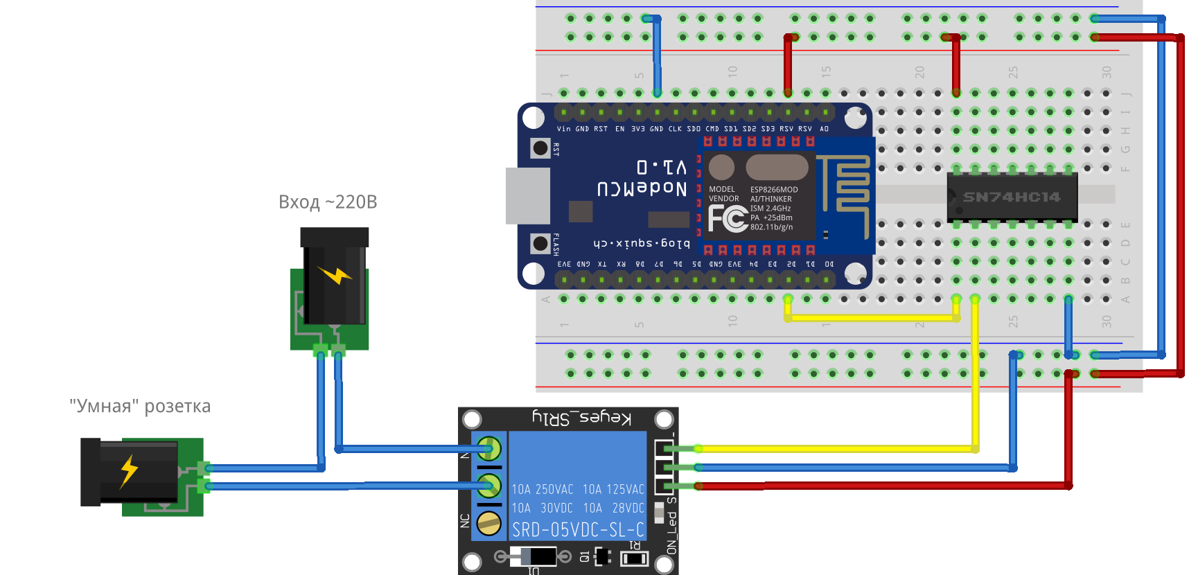
To reproduce the hardware complex described in this example, we strongly recommend following the requirements of the regulations in the field of occupational health and safety, electrical safety, and fire safety. In the absence of the necessary competencies, personal protective equipment, serviceable and safe components, we strongly recommend contacting specialists in the relevant field.
Description of the model
In the model of this example esp8266_smart_socket.engee 4 blocks are used C Function for interaction with the periphery:
WiFiConnect- establishes a WiFi connection using the SSID and password specified in the user sketch. If the connection is not established withinResp_Time_ms = 15000 мсrestarts the WiFi module.NTP_Client- initializes and polls the NTP server, sends it to the outputsHH,MMandSSinteger values of the current hours, minutes, and seconds. During the modeling process, the blockNTP_Clientgenerates a cyclic time change, which allows you to test the operation of the algorithm.ToSerial- initializes the serial port with a transfer rate of 115200 baud, outputs messages to the serial port.GPIO4- initializes digital pin No. 4 of the microcontroller (pin D2 on the debugging board) as an output, sets its statusstate.
Explanations of the custom block code C Function given in the comments of the code.
The model structure of this example is shown in the figure below.
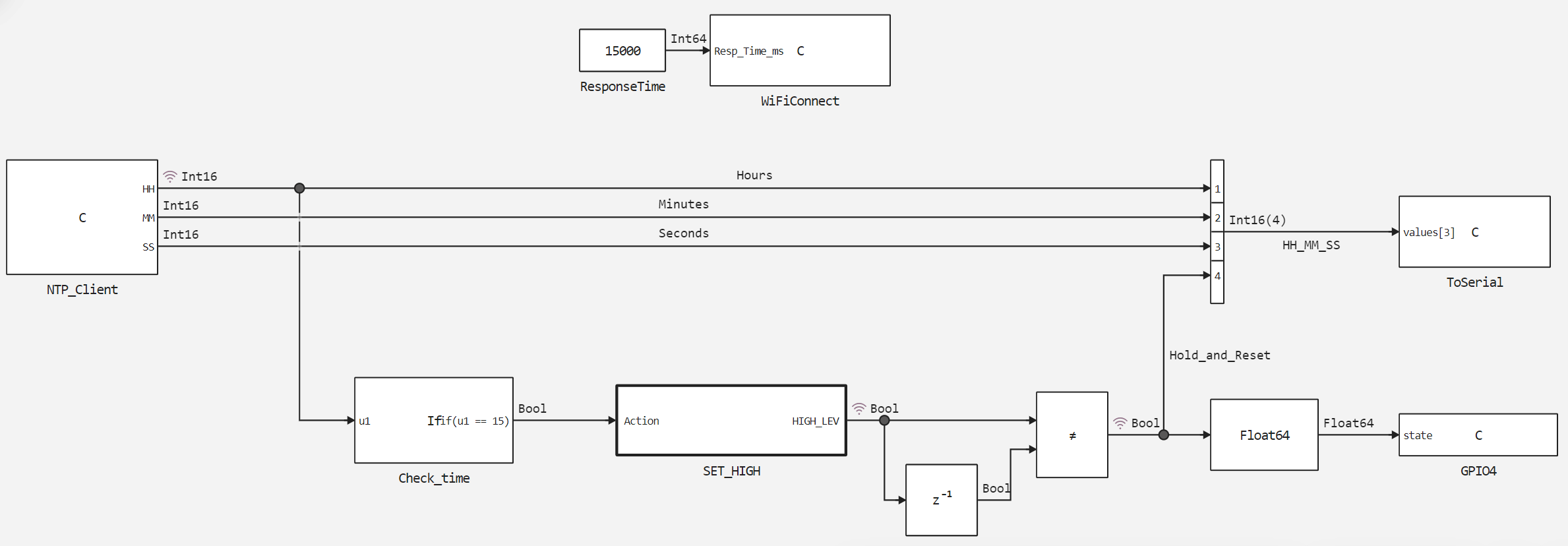
The conditions block Check_time checks the value Hours at the entrance, the condition written in it is equal to 15. If the condition is met, it initiates the execution of the atomic subsystem. SET_HIGH by the execution control port.
Due to the fact that when removing the logical unit from the input Action port exit status HIGH_LEV subsystems SET_HIGH However, in the execution mode of this subsystem, an algorithm for generating single pulses is implemented, which changes the logical output level of the subsystem at each calculation step. In order to hold the signal in case of subsystem execution and reset if it is not executed, the "EXCLUSIVE OR" function is implemented at the subsystem output, which compares the current and previous output values of the subsystem.
Simulation results
Let's check how the algorithm works by uploading and executing the assembled model.
if "esp8266_smart_socket" in [m.name for m in engee.get_all_models()]
    m = engee.open( "esp8266_smart_socket" );
else
    m = engee.load( "$(@__DIR__)/esp8266_smart_socket.engee" );
end

data = engee.run(m);
Let's plot the changes in the current hour - the signal Hours and the relay switching signal - Hold_and_Reset.
using Plots
plotlyjs()
plot(data["Hours"].time, data["Hours"].value,
    label="Time, hours", size=(900,300), lw=2, st=:step)
plot!(data["Hold_and_Reset"].time, data["Hold_and_Reset"].value,
    label="Sockets on", size=(900,300), lw=2, st=:step)
As can be seen from the graphs, when the current hour is cycled, the relay control signal switches and holds the state of the logical unit only at 15 o'clock. Now let's look at the execution of the model on the target device.
Uploading the code to ESP 8266
To upload to ESP 8266, you must first generate the code from the developed model.
engee.generate_code( "$(@__DIR__)/esp8266_smart_socket.engee",
                     "$(@__DIR__)/esp8266_smart_socket_code")
We will connect the files generated in the specified directory in the user sketch. esp8266_smart_socket.ino. Macros and variables are also defined in the sketch, libraries and the ntp server are connected, and the calculation cycle delay is set. Download these files and upload them to ESP8266 using Arduino IDE.
For this example, external libraries are used with: NTPClient, ESP8266WiFi, WiFiUdp. The NTP server is accessed at "pool.ntp.org ".
Explanations of how the user sketch code works are given in its comments.
Code execution on ESP 8266
After successfully compiling the user sketch and uploading the code to the controller, the following diagnostic output can be observed in the monitor of the Arduino IDE port:
The "Socket is on" message in the diagnostic output is accompanied by the switching on of the input status LED on the relay module and switching of the relay power contacts.
Conclusion
This demo discusses the development of the Engee model and its subsequent execution on the target device, the ESP 8266 controller. This model implements interaction with the controller's peripherals - a serial port, a digital output, and a WiFi module, as well as implements NTP server polling and processing of received values. The result of the work of the model and the program based on it is a reproduced principle of operation of a "smart" outlet.