Counter
In this example, we will develop and test a counter model that supports Verilog code generation, as well as test its performance using a cloud compiler.
Let's start by analyzing the implemented model. This is a simple model made using basic blocks. It supports code generation, including a code generation template for a block of comparison operators. The generation template itself is presented below.
This code is a Chisel code generator designed to generate a block of a logical operator (for example, ==, !=, <, >). It uses built-in helper functions and labels (for example, //!, /*!) to generate the Verilog code.
//! BlockType = :RelationalOperator
//! TargetLang = :Chisel

/*! #----------------------------------------------------# */
/*! @Definitions
function show_chisel_type(x::typ) :: String
  if x.bits == 1 && x.fractional_bits == 0
  	out = "Bool()"
  elseif x.fractional_bits == 0
  	out = (x.is_unsigned ? "U" : "S") * "Int($(x.bits).W)"
  else
  	out = "FixedPoint($(x.bits).W,$(x.fractional_bits).BP)"
  end
  out
end
function show_chisel_type(x::signal) :: String
  base_type = show_chisel_type(x.ty)
  len = x.rows * x.cols
  len == 1 ? base_type : "Vec($(len), $(base_type))"
end
*/
val $(output(1)) = Wire($(show_chisel_type(output(1))))
/*! #----------------------------------------------------# */
/*! @Step
function patch_op(op)
  op == "==" ? "===" : op == "~=" ? "=/=" : op
end
function get_idx(len, blen)
  if len == 1
      return ""
  elseif len == blen
      return "(i)"
  else
      return "(i % $(len))"
  end
end
function maybe_zext(sig, sig2)
  if sig.ty.is_unsigned && !sig2.ty.is_unsigned
      return ".zext"
  end
  ""
end
function impl(sig1, sig2, op, out)
  dim0 = dim(out)
  dim1 = dim(sig1)
  dim2 = dim(sig2)
  blen = lcm(dim1, dim2) # broadcasted length
  if blen == 1
      loop_decl = ""
  else
      loop_decl = "for (i <- 0 until $(blen)) "
  end
  "$(loop_decl)$(output(1))$(get_idx(dim0, blen)) := \
      $(sig1)$(get_idx(dim1, blen))$(maybe_zext(sig1, sig2)) \
       $(patch_op(op)) \
      $(sig2)$(get_idx(dim2, blen))$(maybe_zext(sig2, sig1))"
end
*/
$(impl(input(1), input(2), param.Operator, output(1)))
/*! #----------------------------------------------------# */
The code is a step-by-step description of the block.
1. Definition of functions (block @Definitions)
show_chisel_type(x::typ)
Defines how to represent the type x in Chisel syntax:
Bool()if it is a 1-bit boolean value.UInt(...)orSInt(...)if it is an integer type (without a fractional part).FixedPoint(...)if there is a fractional part (fixed point).
show_chisel_type(x::signal)
If the signal is an array (Vec), then returns Vec(n, base_type) Otherwise , just base_type.
2. Announcement of the output signal
val $(output(1)) = Wire($(show_chisel_type(output(1))))
Создаёт выходной сигнал как Wire(...), тип которого определяется по описанным выше функциям.
3. Генерация тела блока (блок @Step)
patch_op(op)
Преобразует операторы в синтаксис Chisel:
"=="→"===""~="→"=/="(неравенство)
get_idx(len, blen)
Используется для обращения к индексам при векторной (массивной) логике:
- возвращает
"", если скаляр. (i), если длины совпадают.(i % len), если требуется broadcasting.
maybe_zext(sig, sig2)
Если один из сигналов — unsigned, а другой — signed, возможно, требуется zext (расширение нулями до совместимого формата).
impl(sig1, sig2, op, out)
Основная функция генерации строки:
- определяет размеры сигналов и их broadcast длину;
- при необходимости оборачивает в
for-цикл. - формирует присваивание вида
output(i) := input1(i) <op> input2(i)
with processing zext, indexes and translation of operators.
This code implements a universal Chisel block generator for logical operations with support for vector signals, broadcasting, and type conversion. It is compiled into Chisel code for hardware description of blocks, for example, for FPGA or ASIC.
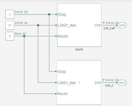
Next, let's look at the implemented model itself and its generation settings.
As we can see, the model is quite simple and has three input ports.:
- the step with which the counter increment is performed;
- the limit of the maximum allowable value of the counter;
- Reset the counter.
Now that we have figured out the model, we will generate its code and verify the resulting code based on the generated C function and based on the handwritten Verilog test bench, after adding a folder with compare.cgt en route Engee.
function run_model(name_model)
    Path = string(@__DIR__) * "/" * name_model * ".engee"

    if name_model in [m.name for m in engee.get_all_models()] # Checking the condition for loading a model into the kernel
        model = engee.open( name_model ) # Open the model
        model_output = engee.run( model, verbose=true ); # Launch the model
    else
        model = engee.load( Path, force=true ) # Upload a model
        model_output = engee.run( model, verbose=true ); # Launch the model
        engee.close( name_model, force=true ); # Close the model
    end
    return model_output
end

run_model("Counter_C_test")
Cnt_ref = simout["Counter_C_test/Cnt_ref"].value;
Cnt_C = simout["Counter_C_test/Cnt_C"].value;
plot(Cnt_ref)
plot!(Cnt_C)
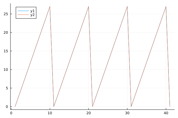
As we can see, the results of working with the code and the source model are identical, which indicates that the code generator is working correctly.
Now let's move on to writing a test binding of our generated code.
module count_Count(
input         clock,
              reset,
input  [31:0] io_Step,
              io_Limit_max,
input         io_Reset,
output [31:0] io_Cnt
);

reg  [31:0] UnitDelay_state;
wire [31:0] Switch =
  $signed(UnitDelay_state) > $signed(io_Limit_max) | io_Reset ? 32'h0 : UnitDelay_state;
always @(posedge clock) begin
  if (reset)
    UnitDelay_state <= 32'h0;
  else
    UnitDelay_state <= io_Step + Switch;
end // always @(posedge)
assign io_Cnt = Switch;
endmodule

module testbench;
reg clock;
reg reset;
reg [31:0] io_Step;
reg [31:0] io_Limit_max;
reg io_Reset;
wire [31:0] io_Cnt;

// Instantiate the module under test
count_Count dut (
  .clock(clock),
  .reset(reset),
  .io_Step(io_Step),
  .io_Limit_max(io_Limit_max),
  .io_Reset(io_Reset),
  .io_Cnt(io_Cnt)
);

// Clock generation
always 5 clock = ~clock;

// Test sequence
initial begin
  // Initialize signals
  clock = 0;
  reset = 1;
  io_Step = 3;
  io_Limit_max = 27;
  io_Reset = 0;

  // Display header
  $display("tStep\tLimit\tCnt");
  $monitor(io_Step, io_Limit_max, io_Cnt);

  // Apply reset
  10 reset = 0;

  // Run simulation until counter wraps around
  200;
  $finish;
end
endmodule
Module testbench It is intended for checking the operation of the counter. Below we list the actions that he performs.
- Initializes the signals:
clock= 0;reset= 1;io_Step= 3;io_Limit_max= 27;io_Reset= 0.
- Generates a clock signal with a period of 10 clock cycles.
- Deactivates the signal after 10 clock cycles
reset. - Outputs values
io_Step,io_Limit_maxandio_Cntto monitor the behavior of the counter. - Completes the simulation after 200 clock cycles.
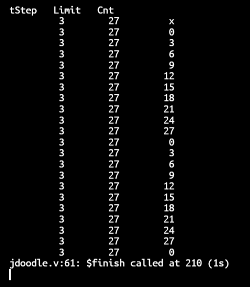
Now let's run our test using the JDoodle Verilog Online website. It is a convenient online platform for writing, compiling and running Verilog code directly in the browser.
# display(MIME("text/html"),
# """<iframe
# src="https://www.jdoodle.com/execute-verilog-online"
# width="750" height="500"
# style="border: none;">
# </iframe>""")
.png)
Conclusion
The simulation results indicate that the code is working correctly.
And it is similar to the results obtained in the model. This means that the generated counter can be used in FPGA operation.