Code generation for Arduino (Traffic lights on finite state machines)
In this example, we will develop a model in Engee for controlling a three-section traffic light for Arduino-compatible boards using the library Finite automata.
Introduction
The purpose of this example is to develop a control model for a three-section traffic light according to a time diagram. The control algorithm will be implemented using the block Chart, and the removal of input and generation of output signals - in blocks C-Function.
For a comprehensive demonstration of the library's capabilities The Engee finite automata, including during subsequent code generation, will operate in two modes in the traffic light control algorithm - the working mode (sections turn on alternately) and the duty mode (the yellow light section turns on and off). The modes will be switched based on a discrete input signal from the target device.
Hardware part
This demo uses an Iskra Neo controller from Amperka. The controlled circuit is assembled from radio components - LEDs, a push-button contact, resistors and connecting wires on a solderless breadboard, as shown in the layout diagram below.
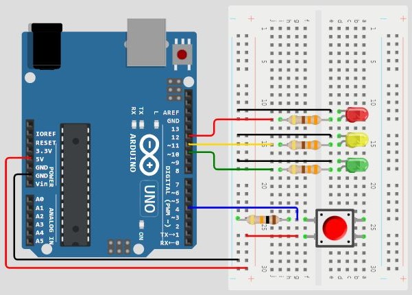
The input signal to turn on/off standby mode is provided by a push-button contact to digital pin 4 of the Arduino board. The output signals for switching on the traffic light sections are provided by digital contacts 10-12 to LEDs of the appropriate colors. Current-limiting (330 ohms) and tensioner (10 kOhm) resistors are also used for the correct operation of the circuit. The circuit receives power from the Arduino board itself.
Time chart
The implemented algorithm will reproduce the operation of the traffic light according to the following time diagram.
At the beginning of the operating mode cycle, the red section of the traffic light lights up for 10 seconds. In the last 3 seconds of its operation, the yellow section lights up in parallel. After this time, the green section lights up for 10 seconds. After that, the green section flashes for 5 seconds, while its on and off periods last for 1 second. After the flashing ends, the yellow section lights up for 3 seconds. After that, the cycle of the operating mode begins anew.
For clarity, the described diagram is shown in the figure below.
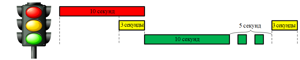
The standby cycle is described by two traffic light states:
- the yellow section is on for 1 second,
- all sections are off for 1 second.
Description of the model
The model of this demo consists of five blocks, as shown in the screenshot of the model below.
The control algorithm, as mentioned earlier, is reproduced by the block Chart. This block has one entrance mode for the operating mode switching signal and two outputs cnt and light to output the signal of the traffic light counter and the code of the illuminated sections, respectively. The controller's peripherals are initialized and controlled using blocks C Function: Digital Input - to transfer the status of the digital input of the controller to the model, Digital Output - to output the status of sections to the digital outputs of the controller, To Serial - for data output via the serial port of the controller. A detailed description of how these blocks work is given in the comments of their code.
For successful block code generation Digital Input An input signal must be transmitted to it. The example uses a block for this. Constant.
State diagram
In the block state diagram Chart There are six states: five for the operating mode (Red, RedAndYellow, Green, Blink, Yellow) and one for the office (BlinkOn).
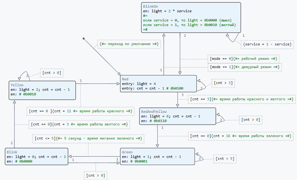
In each state, the counter is decremented. cnt and setting the status of traffic light sections light. The counter is installed and the conditions for changing the state of the traffic light sections are checked in the transitions between the states. Chart.
The block signal table is shown below. Chart.
.png)
Variable light transmits the binary state of the output pins of the target device. The bit number 0 in this variable corresponds to the green section of the traffic light, the bit number 1 is yellow, and the bit number 2 is red. For example: when light = 4 = 0b0110 where the bits numbered 1 and 2 take the value "1", the red and yellow sections will be turned on at the traffic light.
The traffic light operation mode changes between the states Red and BlinkOn depending on the value of the input variable mode.
Variable service it is local to the block Chart and it serves to switch the state. BlinkOn
Simulation results
Let's load the described model:
if "arduino_traffic_lights" in [m.name for m in engee.get_all_models()]
    m = engee.open( "arduino_traffic_lights" );
else
    m = engee.load( "$(@__DIR__)/arduino_traffic_lights.engee" );
end

data = engee.run(m);
From the obtained model data, we will plot the counter variables. cnt and the status code of the traffic light sections light:
using Plots
plotlyjs();
plot(data["Chart.cnt"].time, data["Chart.cnt"].value,
    label="Counter", size=(900,300), lw=2, st=:step)
plot!(data["Chart.light"].time, data["Chart.light"].value,
    label="Light", size=(900,300), lw=2, st=:step)
xlims!(0.0,40.0)
The displayed graph shows the change in variables. The calculation period in the model is set to 1 second. Changing the state variable of traffic light sections light the value and duration correspond to the time chart.
Uploading code to Arduino
To transfer the developed model to the target device, we will generate a C code.:
engee.generate_code( "$(@__DIR__)/arduino_traffic_lights.engee",
                     "$(@__DIR__)/arduino_traffic_lights_code" )
In the specified directory arduino_traffic_lights_code the pluggable files were generated. Also in the directory of the demo example arduino_traffic_lights a pre-written Arduino sketch with the name of this directory has been posted. arduino_traffic_lights.ino. It connects the header file obtained during code generation, initializes global variables, defines the model calculation cycle, and calls the model calculation functions. A detailed description of the sketch is given in the comments of its code.
To execute the code on Arduino, you need to download the directory arduino_traffic_lights and upload the sketch arduino_traffic_lights.ino from the Arduino IDE to the target device.
Code execution on Arduino
After successful compilation and uploading of the sketch to the target device, signals will be generated at the digital outputs of the debugging board to turn on the traffic light sections (LEDs on the breadboard). In order to make sure that the model is working correctly, open the serial port monitor in the Arduino IDE.
.png)
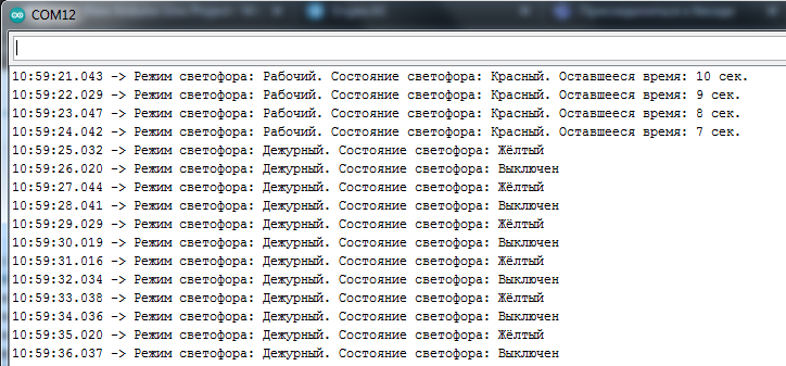
It can be seen that the data specified in the block is output to the serial port. To Serial messages in the required format with a frequency of 1 second.
When you press the button contact with the red LED on, the traffic light switches to standby mode, and the following messages are output to the serial port:
.png)
The required message is output to the serial port with a frequency of 1 second. Therefore, the operation of the traffic light in standby mode is also correct, which confirms the operability of the model and code.
Conclusion
In this demo, a three-section traffic light model was developed for Arduino-compatible platforms. The control algorithm is recreated using the library of finite automata. The model reproduces the operation of the traffic light in two modes, while ensuring not only the switching of sections, but also their flashing. The algorithm's performance has been tested on the target device, and the resulting code not only controls the LED sections, but also transmits messages to the serial port about the current mode, the lit sections, and the remaining operating time of the section.