Code generation for MIC32 (Light Meter)
This demo shows the development of the Engee model for a photoresistor-based light meter, followed by code generation and execution on a MIK32 NUKE V0.3 debugging board.
Introduction
The target device used in this demo is the MIK32 NUKE V0 debugging board.3 based on microcontroller [K1948VK018 MIK32 Amur](https://mikron.ru/products/mikrokontrollery/mk32-amur /). In the Engee model developed in this example, the illumination is calculated using a simulated signal from the analog-to-digital converter (ADC) of the controller, and the controller's peripherals are connected. The code was compiled and uploaded to the microcontroller from VS Code with the PlatformIO extension.
Hardware part
The illumination measurement in this example is performed using фоторезистора from the GL55 family. The input signal of the ADC is the voltage drop across the current-limiting resistor in the photoresistor circuit. In high light conditions, the resistance of the photoresistor decreases, and the voltage drop on the current limiting resistor increases. The supply voltage level is . The connection diagram of the elements is shown below.
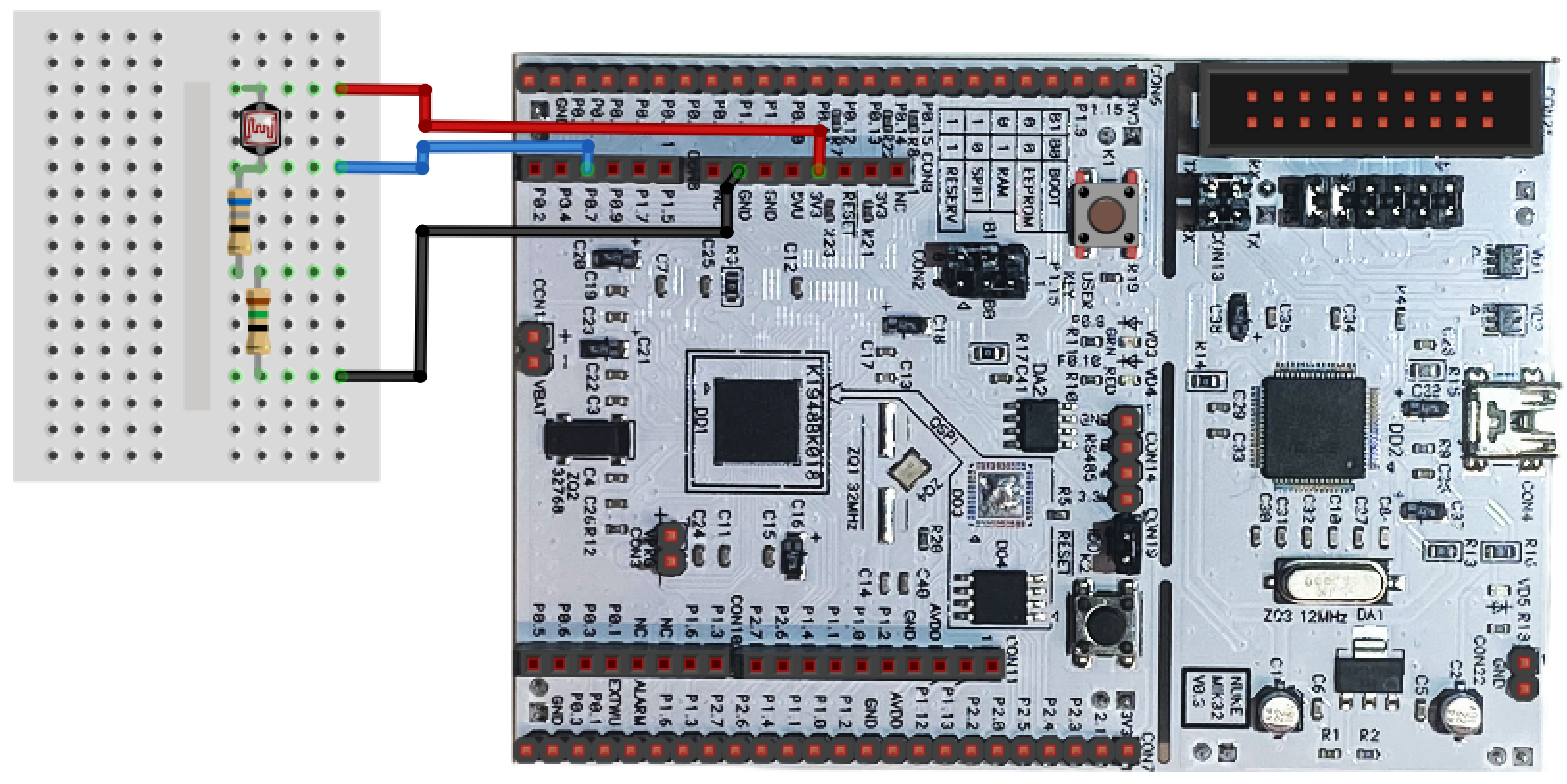
The circuit is powered by a debugging board (contacts 3V3, GND). The analog signal received from the circuit is sent to the ADC of 4 microcontrollers (ADC1.4), contact P0.7.
Description of the model
The model of this example - mik32_adc_lux.engee. The following blocks are used to connect and work with the microcontroller's peripherals: C Function. Simulation Time Block Clock transmits to the block ADC4 current simulation time to simulate the measured value on the resistor voltage drops during simulation.
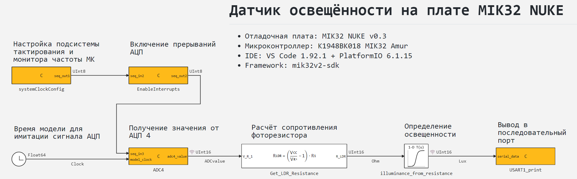
To calculate the illumination in the model, there is a subsystem for calculating the resistance of the photoresistor. Get_LDR_Resistance and the [approximate one-dimensional function] block(https://engee.com/helpcenter/stable/en/base-lib-tables/1d-lookup-table.html ) illuminance_from_resistance.
Connecting peripherals
To work with the MIC32 peripherals, the model uses the following blocks C Function: systemClockConfig, EnableInterrupts, ADC4 and USART1_print. Each of these blocks connects a header file for the corresponding peripheral from the MIK32 HAL library. Block EnableInterrupts among other things, it connects the header file with the interrupt handling function, and USART1_print - header file stdlib.h the C standard library for converting an integer format to a string.
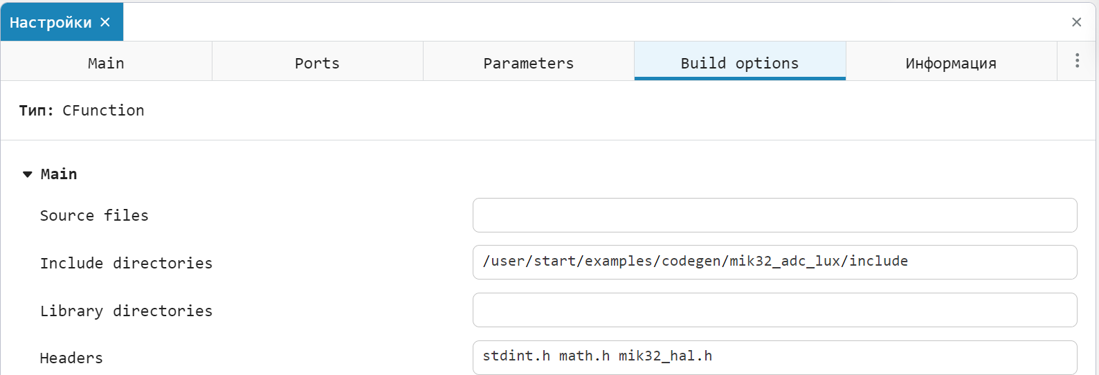
The header files to be connected are contained in the directory include/ an example. The following is an example of connecting the HAL library header file in the block systemClockConfig.
The table below provides information about the purpose of the blocks. C Function and the MIK32 HAL library files they connect.
Block C Function |
Purpose | Pluggable header files |
|---|---|---|
systemClockConfig |
Initialization of the HAL library, configuration of the clock subsystem and the MC frequency monitor | mik32_hal.h |
EnableInterrupts |
Enabling hardware interrupts, enabling the interrupt handling function | mik32_hal_irq.h mik32_hal_adc_isr.h |
ADC4 |
Configuring the ADC and getting new values | mik32_hal_adc.h |
USART1_print |
Configuring the USART and sending messages to it | mik32_hal_usart.h |
A more detailed description of how the code works in blocks C Function given in the comments to the code.
Calculation of illumination
The built-in MIC32 ADCs have a 12-bit bit rate, and therefore the signal received from the ADC ADCvalue accepts values in the range [0, 4095]. As mentioned earlier, this signal corresponds to a voltage drop. on a current-limiting resistor in the photoresistor circuit in the range [0, 1.2] V. In the block Get_LDR_Resistance Based on this signal, the photoresistor resistance is calculated. according to the formula
Based on the received signal Ohm block 1-D Lookup Table illuminance_from_resistance generates an illumination output signal Lux. An example function parameterized by the block illuminance_from_resistance and the coupling of illumination and resistance is determined by the following points:
Illumination = [4624,1895,1412,1129,929,773,646,538,445,363,290,223,162,107,55,7];
Resistance = [1,50,100,150,200,250,300,350,400,450,500,550,600,650,700,750];

using Plots, LaTeXStrings
gr( size = (400, 400), legend=:top, format=:svg )

plot(Resistance, Illumination;
     label = L"Lux = f(R_{LDR})", marker = (:circle, 3, :blue),
     xaxis = ("Photodiode resistance, Ohms"), yaxis = ("Illumination, Lux"))
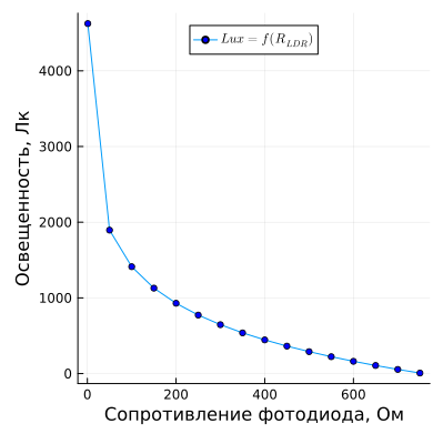
These points are derived from the passport data for the GL55 family of photoresistors.
Simulation results
To simulate the light meter download and run the model mik32_adc_lux.engee:
if "mik32_adc_lux" in [m.name for m in engee.get_all_models()]
    m = engee.open( "mik32_adc_lux" );
else
    m = engee.load( "$(@__DIR__)/mik32_adc_lux.engee" );
end

data = engee.run(m);
From the simulation data obtained, we will plot the signals: the value obtained from the ADC (simulation of a sinusoidal voltage drop change) and the calculated illumination. As in the block 1-D Lookup Table The "nearest" approximation method is selected. As a result of calculations, the illumination will take only those values that were entered into the block table.
gr( size = (800, 300), legend=:top, format=:svg )
plot(данные["ADCvalue"].time, данные["ADCvalue"].value;
     label = "ADC Data", lw = 2)
plot!(данные["Lux"].time, данные["Lux"].value*4;
      label = "Illumination, 4⋅lux", st = :step, lw = 2)
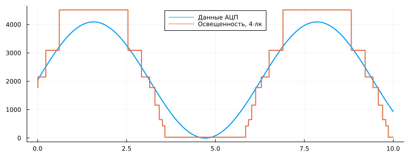
As can be seen from the graphs obtained, a change in the signal from the ADC leads to corresponding changes in the calculated illumination signal.
Code generation
Generate код from the model for subsequent loading of the algorithm developed in the model into the microcontroller:
engee.generate_code( "$(@__DIR__)/mik32_adc_lux.engee",
                     "$(@__DIR__)/mik32_adc_lux_code")
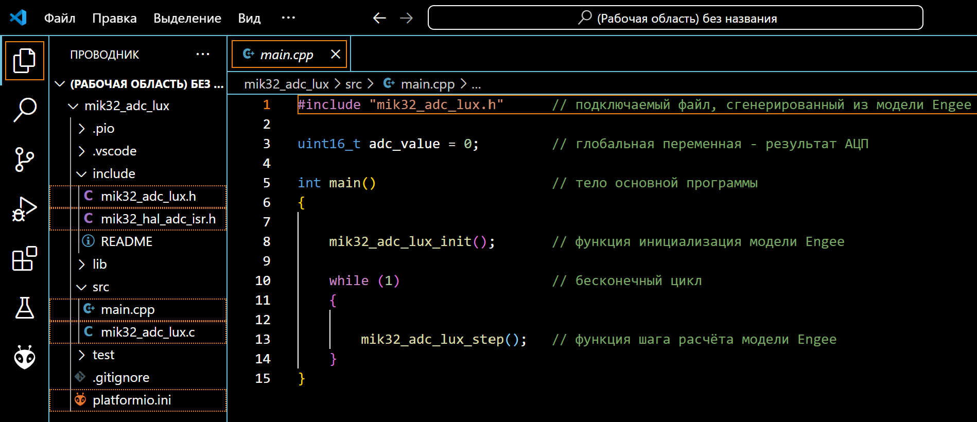
Created in the folder mik32_adc_lux_code header files mik32_adc_lux.h and the original mik32_adc_lux.c we continue to use it when building the project. Generated main program file main.c It will not be used in the project. It has been prepared for code execution in the development environment. main.cpp located in the root folder mik32_adc_lux an example.
Project preparation in the development environment
The development environment through which the project is built and uploaded to the target device is VS Code with the PlatformIO add-on. The environment and connection configurations are not considered in this example, as they are described in detail on ресурсах the developer of the controller.
From the sample directory, we will transfer the generated files to the PlatformIO project., main.cpp, mik32_hal_adc_isr.h and the configuration file platformio.ini.
After that, you can proceed to build the project and download the program.
Code execution on MIC32
Connect the debugging board MIK32 NUKE V0.3 to the USB port of the computer, after which we can observe the connected device in PlatformIO. A USB driver is required to correctly identify the connection of this card. The example uses the driver libusbK.
After successful activation, we will proceed to building the project.:
“PLATFORMIO -> PROJECT TASKS -> mik32v2 -> General -> Build”.
If there are no build errors, we will upload the compiled code to the microcontroller.:
“PLATFORMIO -> PROJECT TASKS -> mik32v2 -> General -> Upload”.
To output the calculation results, we use the graph builder from the SerialPlot program, which receives data from the serial port.
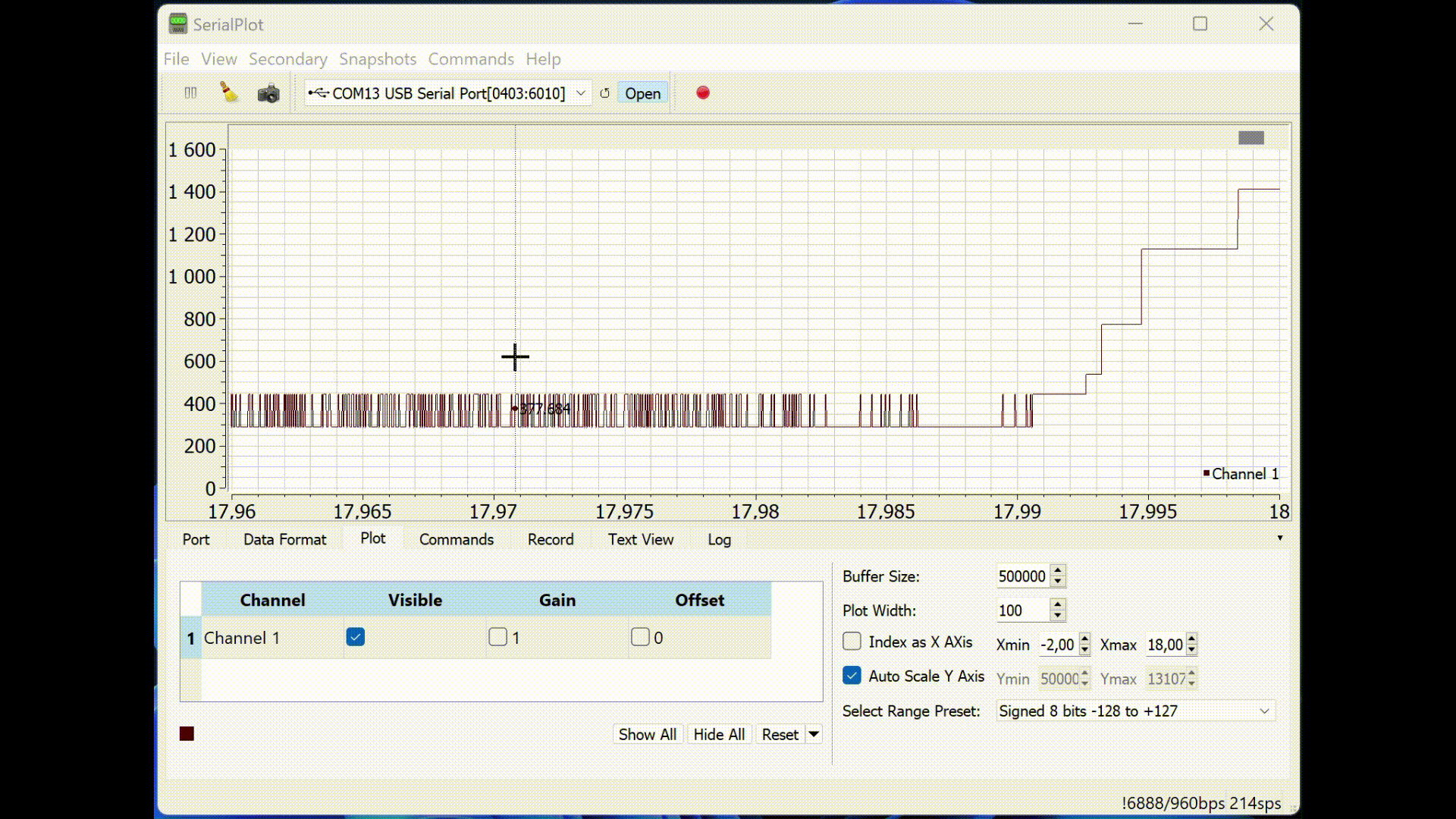
When the illumination on the photodiode changes (by shining a flashlight on it or shading it), the corresponding illumination value from the unit is output to the serial port. Lookup Table models.
Conclusion
In this example, we examined the development of the Engee model for an illumination calculation program based on the ADC signal and output of the resulting value to the serial port on the K1948VK018 MIK32 Amur microcontroller as part of the MIK32 NUKE V0.3 debugging board. The developed model is embedded with the generated files in the PlatformIO environment project for VS Code, followed by assembly, download, and execution on the target device.