Code generation for MIC32 (Engee logo)
This demo shows the development of the Engee model for issuing vectors with the coordinates of the points that make up the Engee logo to two DAC channels of the MIK32V2 microcontroller.
Introduction
The target device used in this demo is the MIK32 NUKE V0 debugging board.3 based on microcontroller [K1948VK018 MIK32 Amur](https://mikron.ru/products/mikrokontrollery/mk32-amur /). In the Engee model developed in this example, variable signals X and Y are generated on two DAC channels, and the Y(X) function is used to obtain the Engee logo. The code was compiled and uploaded to the microcontroller from VS Code with the PlatformIO extension.
Receiving variable signals
We have already presented the demo пример , drawing the Engee logo.
# Go to the example directory
cd("/user/start/examples/base_simulation/polar_plot_engee_logo/");
# Executing the example script
engee.script.run("/user/start/examples/base_simulation/polar_plot_engee_logo/draw_polar_engee_logo.ngscript");
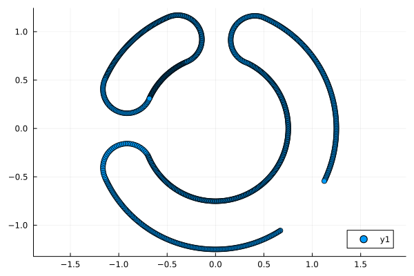
After executing the example script, all the necessary variables should appear in the workspace. Let's plot the resulting logo based on the points.
gr()
plot( s["y"].value, s["x"].value; aspect_ratio=:equal, seriestype = :scatter)
Since the microcontroller's DACs are 12-bit, the variables transmitted to them (the X and Y coordinates of the logo points) must have the format uint16_t and belong to a range of values . Let's shift and scale the points:
# Inverting the values
X = -s["x"].value
Y = -s["y"].value

# Scaling ranges of values
Y_max = maximum(Y)
Y_min = minimum(Y)
Y_rng = Y_max-Y_min
Y = (Y .- Y_min)./ Y_rng .* 4095

X_max = maximum(X)
X_min = minimum(X)
X_rng = X_max-X_min
X = (X .- X_min)./ X_rng .* 4095

# Convert to an integer format
X = convert.(Int,X.÷1);
Y = convert.(Int,Y.÷1);

# Thinning the vectors to save controller memory
New_X = Vector{Int}(undef, 250);
New_Y = Vector{Int}(undef, 250);

for i in 1:length(New_X)
    New_X[i] = X[i*4]
    New_Y[i] = Y[i*4]
end

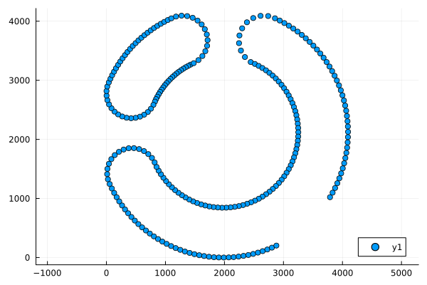
# Let's build a logo based on thinned, scaled values.
plot( New_X, New_Y; aspect_ratio=:equal, seriestype = :scatter)
Description of the model
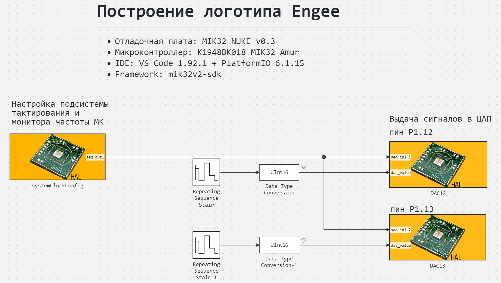
The model of this example - mik32_engee_logo.engee. It is similar to the model mik32_dac.engee the only exception is how the input variables for the DAC are set.

To set the variable signals of the DAC, the obtained variables of the coordinates of the logo points are New_X and New_Y They are written in blocks Repeating Sequence Stair. We can reproduce the model and make sure that the specified points in the model are plotted similarly to the previous graph, but we will not repeat ourselves. Let's move on to code generation.
Code generation and project assembly
# @markdown **Code generation:**
# @markdown A folder for code generation results will be created in the script folder:
cd(@__DIR__)
папка = "code" # @param {type:"string"}
имя_модели = "mik32_engee_logo" # @param {type:"string"}
# @markdown Code generation for the subsystem:
включить = false # @param {type:"boolean"}
if(enable)
    подсистема = "" # @param {type:"string"}
    engee.generate_code( "$(@__DIR__)/"*имя_модели*".engee", "$(@__DIR__)/"*папка;
                     subsystem_name = subsystem)
else
    engee.generate_code( "$(@__DIR__)/"*имя_модели*".engee", "$(@__DIR__)/"*папка)
end
The project with the model is assembled in the IDE VS Code+PlatformIO, the assembly process is similar to the process from the example MIC32: Sawtooth signal generator. Let's move on to executing the code on the microcontroller.
Code execution on MIK 32
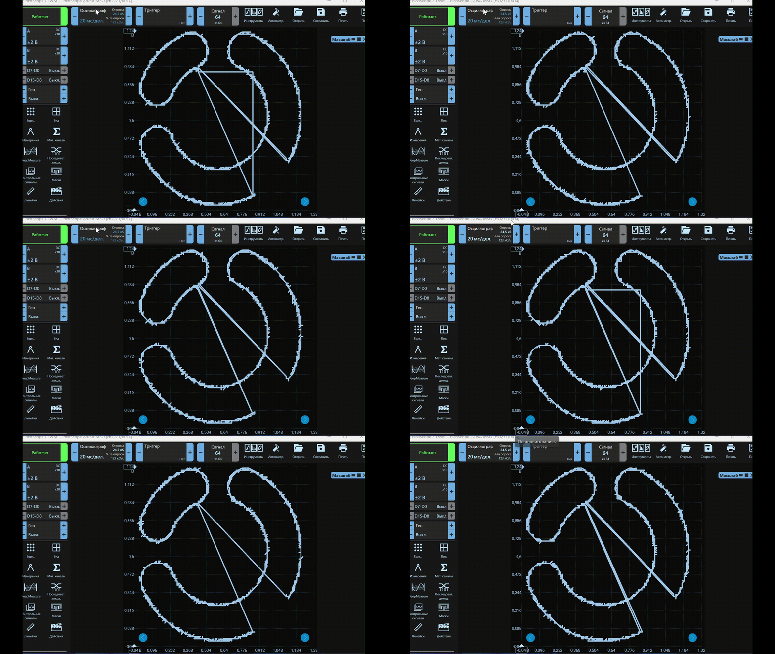
After successful assembly and compilation of the project, we will connect an oscilloscope to both DAC channels of the microcontroller and reflect the oscilloscope in the function Y(X).

As you can see in the animation, the DAC channels reproduce variable signals that build the Engee logo.
Conclusion
We used early developments - examples with the construction of the Engee logo in polar coordinates and working with the DAC of the MIC 32 microcontroller - to organize the output of variables with complex functional dependencies to analog outputs.

