Generating code for Arduino (reading the analog input signal)
In this example, we will generate a code for Arduino that will take a measurement of an analog input value and use this input parameter to control the brightness of the on-board LED.
Introduction
For this demonstration, in addition to the Arduino board, we will need a variable resistor (potentiometer). We will use the Troyka module from the manufacturer Amperka. This potentiometer has a resistance of 10 kOhm and allows you to change the voltage at the signal output from about 0 volts to the Arduino supply voltage (usually 5 volts).
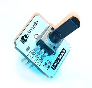
As a rule, any analog potentiometer has three output pins, which we will connect to the Arduino board as follows:
- power pins V (voltage) and G (ground) – to pins 5V and GND of the Arduino board
- pin S (signal) – to pin A0 (zero analog input)
Description of the Engee model
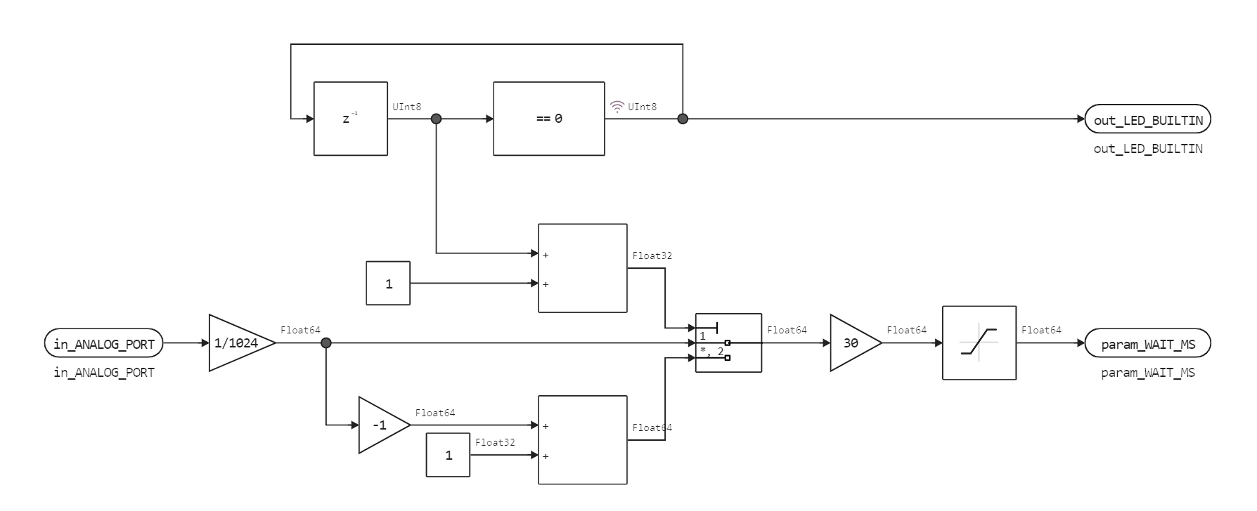
The general view of the model is shown below analog.engee, from which we will generate the code. It consists of one subsystem.
.png)
In one calculation cycle, the model accepts input data through the port in_ANALOG_PORT and calculates two output variables: out_LED_BUILTIN and param_WAIT_MS.
The input variable has a range of values from 0 to 1023 (data comes from a 10-bit ADC), so first we scale it to a range from 0 to 1. Type conversion occurs automatically. Component Multiport Switch alternately returns to us the duration of switching on and the duration of turning off the LED. There is a block after it. Gain where the delay is multiplied by 30, and the block Saturation, which prevents negative values from being transmitted to the output param_WAIT_MS.
Interface Model-Arduino
The platform-dependent part of this code, which is stored in a file sketch_analog_custom/sketch_analog_custom.ino, implements the following interface:
- Reads the input voltage level
A0the Arduino platform transmits this 10-bit value to the input of the model., - accepts the LED status from the model (on or off) and turns on or off the digital output connected to the diode,
- accepts the delay time in milliseconds from the model, which must elapse from the completion of the execution of our model's code to the next execution.
We could generate PWM in other ways.:
- by calling the built-in Arduino function
analogWrite, - or by comparing the desired value with a sawtooth signal.
Code generation
The next cell allows you to exit the model analog.engee make the code that will be placed in the folder sketch_analog_custom/analog_code.
engee.generate_code( "$(@__DIR__)/analog.engee",
                           "$(@__DIR__)/sketch_analog_custom/analog_code" )
The files received at the output *.c and *.h already placed in the required subfolder of the project. File analog.c we connect to the platform-dependent part of the code using the command include.
Data is transmitted to and from the generated code using structures analog_U and analog_Y. The fields of these structures have the same names as the ports in the Engee diagram.
To get a more concise code, try disabling automatic comments in the model settings (Code Generation tab).
Transferring the model to Arduino
To transfer the project to Arduino, follow these steps:
- Download the catalog
sketch_analog_customfrom the file browser; - Unzip the archive on your local computer;
- Open the file
sketch_analog_custom.inoand in the Arduino IDE, click on the buttonUpload.
As a result, we were able to use a potentiometer to adjust the dimming of the PWM signal that goes to the LED, and hence its brightness. Servos, pumps, and various amplifiers can be controlled in the same way (be careful with current consumption restrictions, it is better to connect three or more servos via an additional power source, bypassing Arduino voltage stabilization).
Conclusion
We have seen that in Engee it is possible to create full–fledged algorithms for embedded systems - to receive data, process it, and use output values to control electronics connected to the hardware platform.
Code generation is a critical tool for implementing a model–oriented approach to development, where part of the code of an embedded system can be developed as a model, tested in a model environment, and conducted through semi-routine testing.