Code generation for MIC32 (Binary Counter)
This demo shows the development of the Engee model for a two-bit binary counter, followed by code generation and execution on the MIK32 NUKE V0.3 debugging board.
Introduction
In this example, the MIK32 NUKE V0 debugging board is used as the target device.3 based on microcontroller [K1948VK018 MIK32 Amur](https://mikron.ru/products/mikrokontrollery/mk32-amur /). Engee has developed a model of the end device, a two-bit binary counter, and generated a C code. The code was compiled and uploaded to the microcontroller from VS Code with the PlatformIO extension.
The built-in user button K1 is used as the input of the counter, and the built-in LEDs VD3 and VD4 are used as outputs.
Description of the model
The model of this example - mik32_DI_DO.engee. Functionally, it can be divided into blocks for connecting the controller's peripherals, control logic, and a block for simulating clicks on the user's K1 button.
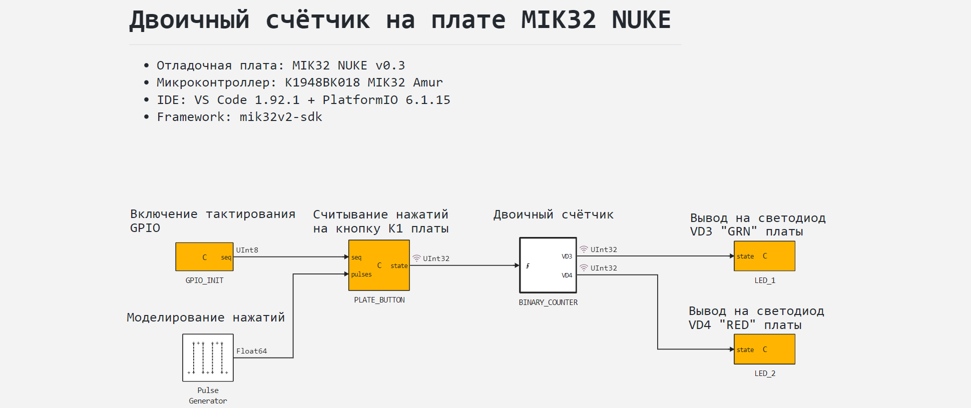
A block for simulating clicks on a custom button - Pulse Generator generates a rectangular signal with a frequency of 1 Hz and a fill factor of 0.5 during simulation. Block C Function "PLATE_BUTTON" transmits this signal to the counter subsystem without changes.
Connecting peripherals
To work with the MIK32 controller peripherals, the model contains the following blocks C Function:
GPIO_INIT- to enable GPIO clocking;PLATE_BUTTON- to initialize the built-in user button K1, to read its statusstate;LED_1- to initialize the built-in LD1 LED, transfer the status to itstate;LED_2- to initialize the built-in LD2 LED, transfer the status to itstate.
Contacts seq blocks GPIO_INIT and PLATE_BUTTON They are used exclusively to determine the sequence of execution of functions that will be obtained from these blocks as a result of model code generation.
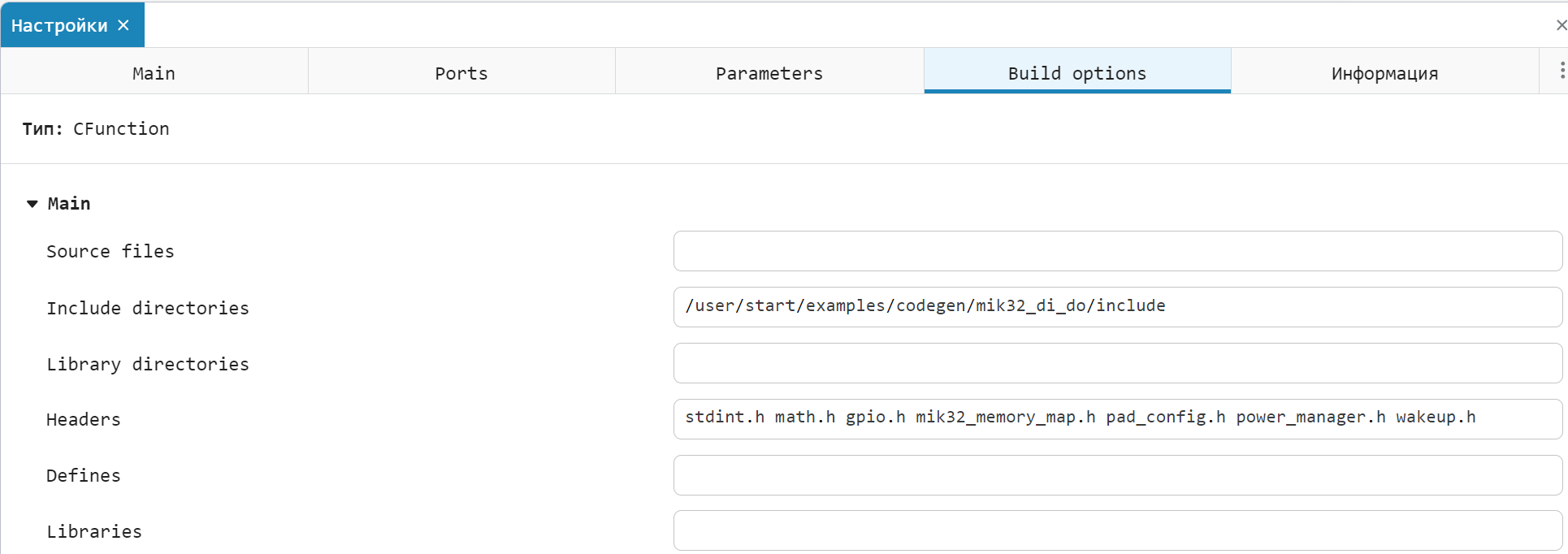
Plug-in files for working with the controller peripherals and successfully compiling the code obtained from the model in the development environment - mik32_memory_map.h, pad_config.h, power_manager.h and wakeup.h located in the directory include the current example. They are connected in the block GPIO_INIT, tab Build options. You do not need to download these files and connect them to the project in the VS Code environment, since if the environment is configured correctly, they are already contained in the corresponding PlatformIO packages.
A detailed description of the principles of the code embedded in C Function given in the comments to the block code.
Binary counter
Binary counter implemented in the subsystem BINARY_COUNTER, works as follows. From the entrance Trigger subsystems per block Chart a signal is received from the selected leading edge of the signal - pressing the K1 button. In the block Chart The number of incoming signals is calculated, and the result of the calculation is output to the output of the out block. The calculation is performed cyclically, in the range [0; 3].
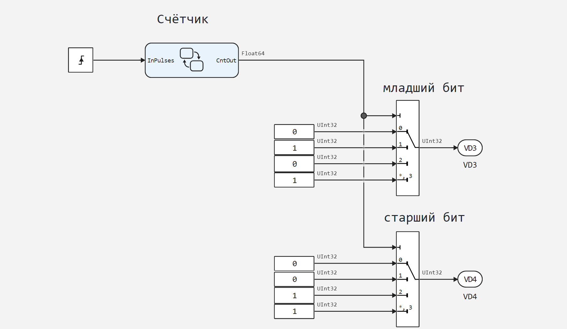
By the output signal of the counter, the blocks Multiport Switch The bit states are switched to control the LEDs VD3 and VD4, thereby acting as encoders of decimal numbers into binary numbers. The least significant bit of the number is formed on VD3, and the most significant bit on VD4. The output data type is an unsigned 32-bit integer (UInt32).
Simulation results
To simulate the operation of a two-bit binary counter, download and run the model mik32_DI_DO.engee:
if "mik32_DI_DO" in [m.name for m in engee.get_all_models()]
    m = engee.open( "mik32_DI_DO" );
else
    m = engee.load( "$(@__DIR__)/mik32_DI_DO.engee" );
end

    data = engee.run(m);
From the obtained simulation data, we will plot the signal graphs:
PLATE_BUTTON.1- imitation of pressing a button,BINARY_COUNTER.VD3- states of the lowest bit of the output code,BINARY_COUNTER.VD4- the status of the highest bit of the output code.
The signals displayed on the graphs have a binary format, but they are scaled for visual clarity.
using Plots
plotlyjs()

plot(data["PLATE_BUTTON.1"].time,
     data["PLATE_BUTTON.1"].value*0.5,
     label="Button signal", lw=1)
plot!(data["BINARY_COUNTER.VD3"].time,
      data["BINARY_COUNTER.VD3"].value*0.99,
      label="The lowest bit", size=(900,300),
      lw=3, legend=:topright)
plot!(data["BINARY_COUNTER.VD4"].time,
      data["BINARY_COUNTER.VD4"].value*1.01,
      label="The highest bit", lw=3)
As can be seen from the simulated graphs, the binary counter algorithm is working correctly, now you can proceed to code generation and execution of the model code on the target device.
Code generation
We will generate the code from the model for subsequent loading of the control algorithm into the microcontroller.:
engee.generate_code( "$(@__DIR__)/mik32_DI_DO.engee",
                     "$(@__DIR__)/mik32_DI_DO_code")
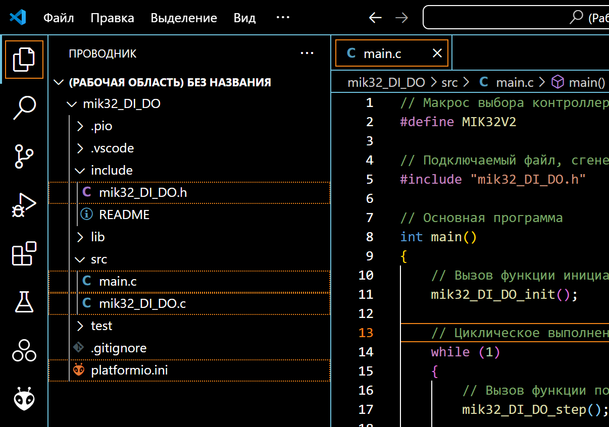
Created in the folder mik32_DI_DO_code header files mik32_DI_DO.h and the original mik32_DI_DO.c we continue to use it when building the project. Generated main program file main.c It will not be used in the project. It has been prepared for code execution in the development environment. main.c located in the root folder mik32_DI_DO an example.
Project preparation in the development environment
The development environment through which the project is built and uploaded to the target device is VS Code with the PlatformIO add-on. The environment and connection configurations are not considered in this example, as they are described in detail on ресурсах the developer of the controller.
From the sample directory, we will transfer the generated files, main.c and the configuration file to the PlatformIO project. platformio.ini.
After that, you can proceed to build the project and download the program.
Code execution on MIC32
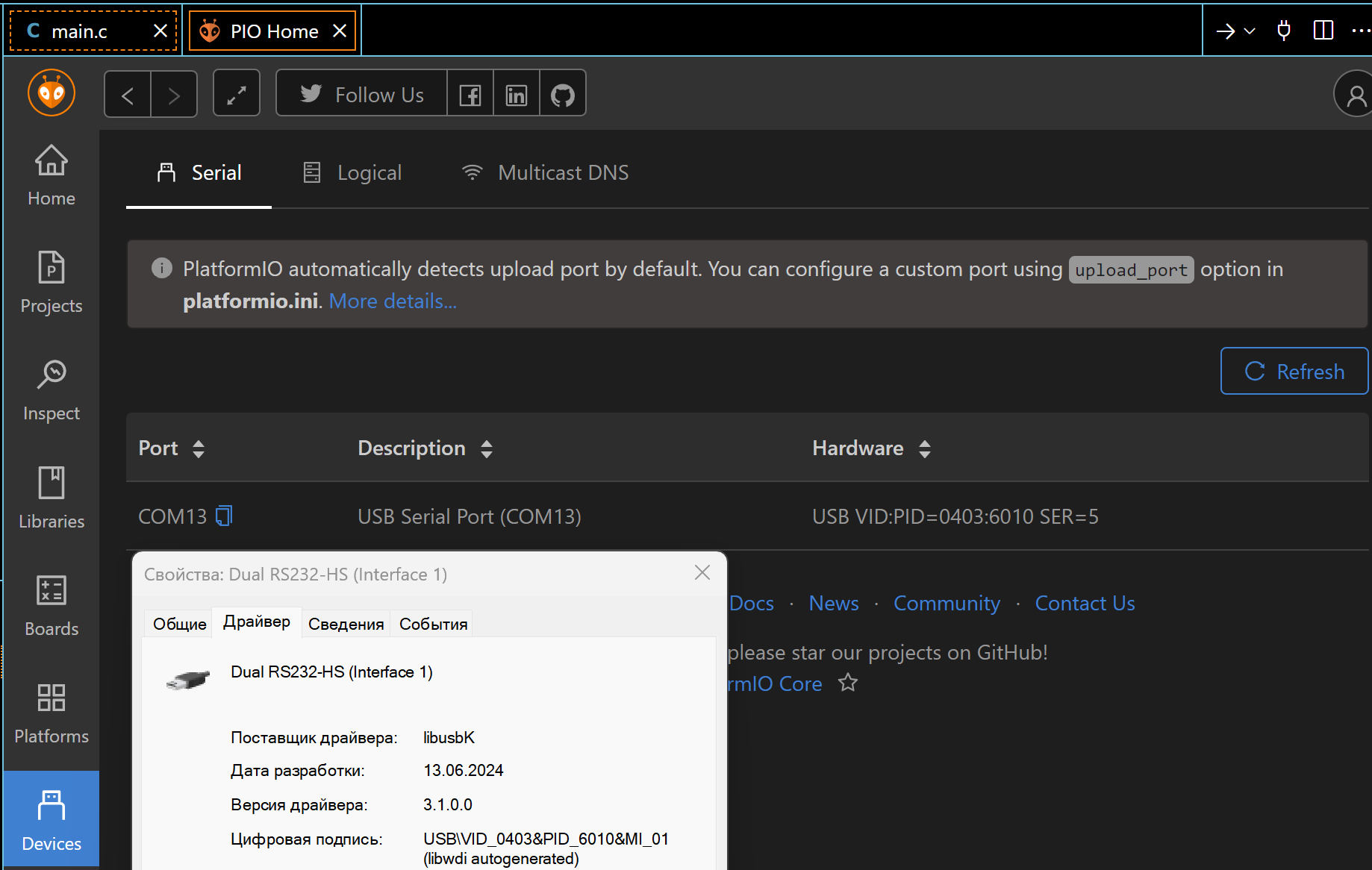
Connect the debugging board MIK32 NUKE V0.3 to the USB port of the computer, after which we can observe the connected device in PlatformIO. A USB driver is required to correctly identify the connection of this card. The example uses the driver libusbK.
After successful activation, we will proceed to building the project.:
“PLATFORMIO -> PROJECT TASKS -> mik32v2 -> General -> Build”.
If there are no build errors, we will upload the compiled code to the microcontroller.:
“PLATFORMIO -> PROJECT TASKS -> mik32v2 -> General -> Upload”.
As a result of executing the code generated from the Engee model, it is possible to observe the formation of a binary code on the built-in LEDs VD3 and VD4 by pressing the built-in button K1. As you can see, the uploaded code reproduces the operation of a two-bit binary counter.
Conclusion
In this example, we examined the development of the Engee model for a program for controlling built-in LEDs based on a signal from a built-in button on the K1948VK018 MIK32 Amur microcontroller as part of the MIK32 NUKE V0.3 debugging board. The algorithm is implemented using the block Chart from the library Engee finite automata and is suitable for code generation. The developed model is embedded with the generated files in the PlatformIO environment project for VS Code, followed by assembly, download, and execution on the target device.