Code generation for Arduino (PWM signal generation)
In this example, we will show how software code for PWM generation on the Arduino platform can be generated in Engee.
Introduction
There are many ways to create a pulse width modulated signal (PWM). We are implementing a basic component model that is as similar as possible to the demo example. arduino_blink. That is, we have to manage the time delay between the events of turning on and off the LED.
Other ways you can use:
- Compare a smoothly changing analog signal with a sawtooth signal and switch the diode at the moment of intersection
- Use one of the built-in Arduino functions
Platform preparation
For this example, we will need an Arduino-compatible platform (Uno, Leonardo, Iskra, and others) and a suitable USB cable. You will also need to install the [Arduino IDE] environment on your computer (https://www.arduino.cc/en/software ), find and supply additional драйверы (if necessary) and connect the existing board via the USB port.
Description of the model
In this example, we will generate code from the model. pwm.engee.
The interface of the model is the same as the interface in the example arduino_blink. At each step of the calculations, she:
- Switches the status of the LED using the output
out_LED_BUILTIN(initially equal to 1, it changes to the "opposite" with each cycle), - Returns the Arduino time delay value using the output
param_WAIT_MS(value in milliseconds).
.png)
The borehole will vary along a sinusoid with the frequency set in the block. Sine. The maximum value is set as the amplitude of the same block, and the offset set there allows the delay value to never become less than 0, which will cause an error on the Arduino platform and stop the program execution.
It is by using the value param_WAIT_MS we will control the pulse frequency by turning on and off the "on-board" LED of the Arduino platform with pulses of different lengths.
The PWM signal is characterized by the fact that during a fixed period it changes state 1 and the condition 0, the duration of which is equal in total to , but the ratio of which is changed using the parameter (borehole).
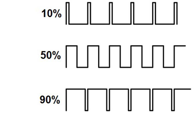
We will use this signal to simulate smooth LED brightness control on the Arduino platform.
Data type conversion
Basically, the blocks of the Engee model are directly reflected in the code for Arduino. Not all platforms use the same C/C++ language standards. Naturally, when creating code, you always have to think about low-level implementation details.
In this example, the problem that we overcome in Engee is automatic typecasting. On the Arduino platform:
- When adding a Boolean data type with a numeric one, the output is a Boolean
- When adding the double data type with an unsigned integer, the output is an unsigned integer (the operation of the sine wave turns out to be incorrect if you do not specify a special data type)
Where are the problems with data types?
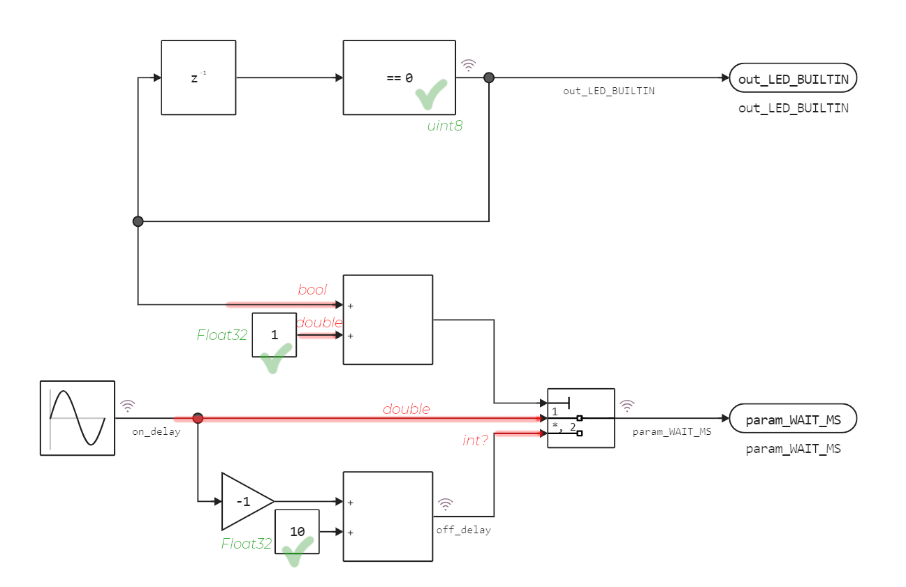
Therefore, we need to anticipate how the data types will work in the C code, and adjust the model blocks (marked with green checkmarks) accordingly:
- Blocks
Constantmust return the data typeFloat32 - Block
Compare To Zeromust not returnbool, anduint8
All these settings are set in the corresponding blocks. Sometimes these problems can be solved using blocks. Data Type Conversion such transformations also go into the generated source code.
Testing the model
The process of semi-natural modeling
involves running the model in a simulated environment for debugging and optimization, followed by monitoring the operation of the same algorithm on a hardware platform.
In our case, it is worth considering that the Arduino operates at its own clock frequency, and different commands can be executed in different numbers of cycles. To rely on real physical time, it is better to create a template for code generation based on a real-time system.
Nevertheless, we can already show how our solution will work.
if "pwm" in [m.name for m in engee.get_all_models()]
    m = engee.open( "pwm" );
else
    m = engee.load( "$(@__DIR__)/pwm.engee" );
end

data = engee.run(m);
Let's plot the delay time for switching the LED (the parameter that is passed to delay()).
using Plots
plot( data["param_WAIT_MS"].time, data["param_WAIT_MS"].value,
      label="param_WAIT_MS", st=:step, size=(900,300))

# Let's touch up the variable delay time (LED on/off)
plot!( data["param_WAIT_MS"].time, [iseven(i) ? d : NaN for (i,d) in enumerate(data["param_WAIT_MS"].value)],
      label="delay when the LED is off", st=:step, size=(900,300), c=:black, lw=2)
plot!( data["param_WAIT_MS"].time, [isodd(i) ? d : NaN for (i,d) in enumerate(data["param_WAIT_MS"].value)],
      label="delay when the LED is on", st=:step, size=(900,300), c=:red, lw=2)
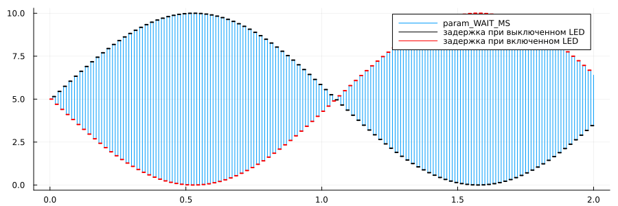
What do we see here? Time delay param_WAIT_MS It changes over time so that every two adjacent values always add up to about 10 milliseconds. The law for modulating this process is set by the sine wave.
If you combine both output signals correctly, then we will see exactly the PWM signal that controls the switching on and off of the current supplied to the output to which the LED is connected.
plot( cumsum(data["param_WAIT_MS"].value),
             data["out_LED_BUILTIN"].value,
      st=:step, size=(900,200))
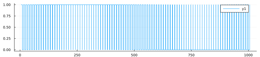
This model is not configured in such a way as to simulate the real time of operations, so you may notice that the model time (2 seconds is the duration of the simulation) is not equal to the processor time (according to the schedule – about 1 second, and then with large allowances). To ensure this property, you need to build the model in a slightly different way.
Code generation
In this demo, we suggest generating the code using the following command:
engee.generate_code( "$(@__DIR__)/pwm.engee",
                     "$(@__DIR__)/sketch_pwm_custom/pwm_code" )
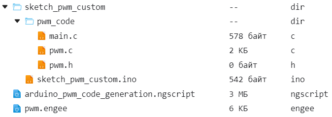
As a result, in the catalog sketch_pwm_custom The folder will open pwm_code in which we find .c and .h files with the code of our model.
Project Files
There is only one model in our project. Of the generated files, we will need only the files with the code of this model: the source code pwm.c and the header file pwm.h.
It is worth paying attention to the structure of the project files and directories.:
.png)
- file
sketch_pwm_custom.inocontains a description of the interface Model-Arduino, - Level catalog
sketch_pwm_customIt should be named the same as the file.*.ino(Arduino IDE requirements), - catalog
pwm_codeit contains files with the generated code, which we will include in the file.*.ino.
Transferring the model to Arduino
To transfer a project to Arduino, the standard steps are as follows:
- Download the catalog
sketch_pwm_customfrom the file browser, unzip the archive - Open the file
sketch_pwm_custom.inoand click on the buttonUpload
The result should be as follows (the LED flickers smoothly):
Conclusion
We have created a slightly more complex model than a flashing LED. This method of creating a PWM signal will allow you to control simple equipment, such as LEDs or servomotors.
We had to take into account how data type conversion works on the target platform. Nevertheless, we have seen that the Engee platform makes it possible to simulate components that can be run almost seamlessly on a hardware platform by generating code.