Code generation for Arduino (Crossroads)
In this example, we will develop a model in Engee for controlling two automobile and one pedestrian traffic lights at the same intersection based on an Arduino-compatible board using the library Finite automata.
Introduction
The purpose of this example is to develop a model for controlling an intersection consisting of two automobile and one pedestrian flows, which are controlled by two three-section and one two-section traffic lights, respectively. The section switching algorithm will be determined according to the time diagram. The control algorithm will be implemented using several blocks. Chart, and the removal of input and generation of output signals - in blocks C-Function.
In the algorithm of the control program, it is possible to choose the mode - working or standby, switching modes will be carried out by a discrete input signal from the target device.
This example is a development of the demo example "Code generation for Arduino (Traffic light on finite automata)". The features of this example in comparison with the previous one are: modeling and code generation of several interconnected blocks Chart and the output of the data array to the peripheral.
Hardware part
This demo uses an Iskra Neo controller from Amperka. The controlled circuit is assembled from radio components - LEDs, a push-button contact, resistors and connecting wires on a solderless breadboard, as shown in the layout diagram below. The scheme simulates the operation of traffic lights: two automobile three-section and one pedestrian two-section.
The input signal to turn on/off standby mode is provided by a push-button contact to digital pin 4 of the Arduino board. The output signals for switching on sections of automobile traffic lights are provided by digital contacts 8-13 to LEDs of the appropriate colors. The output signals for switching on sections of pedestrian traffic lights are provided by digital contacts 6, 7. Current-limiting (330 ohms) and tightening (10 kOhm) resistors are also used for the correct operation of the circuit. The circuit receives power from the Arduino board itself.
Time chart
The implemented algorithm will reproduce the operation of traffic lights at the intersection according to the time diagram below.
Three traffic flows, two automobile and one pedestrian, are controlled asynchronously. In this case, the traffic permit (green light) is generated for only one stream at a time and lasts for 10 seconds. After the end of the traffic permit, the flashing of the green section turns on. The transition of a traffic light from an enabling signal to a forbidding one (red light) is accompanied by the inclusion of the yellow section for 5 seconds, the reverse transition is accompanied by the simultaneous inclusion of the red and yellow sections for 5 seconds.
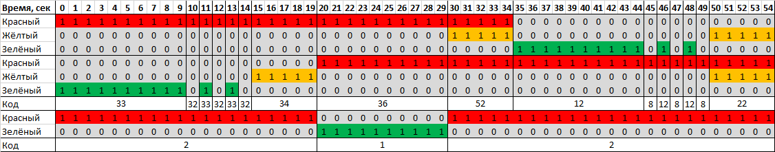
The duty cycle is described by two traffic light states:
- the yellow sections of car traffic lights are on for 1 second, and the pedestrian traffic light sections are off;
- All sections of the automobile and pedestrian traffic lights are switched off within 1 second.
Description of the model
The model of this demo is shown in the figure below.
The control algorithm is divided into functional parts - the operation of the counter is reproduced in the block Common_Counter, control signal generation light for car traffic lights - in the block Traffic_Lights, control signal generation cross for pedestrian traffic lights - in the block Crosswalk.
To transmit the mode selection signal to the model, the block is used Digital Input to output messages to the serial port of the Arduino block To Serial, and for outputting car and pedestrian traffic light codes to digital Arduino pins , there are blocks Digital_Output_1 and Digital_Output_2 accordingly.
A vector generation unit is used for structured data output to the serial port. DataMux.
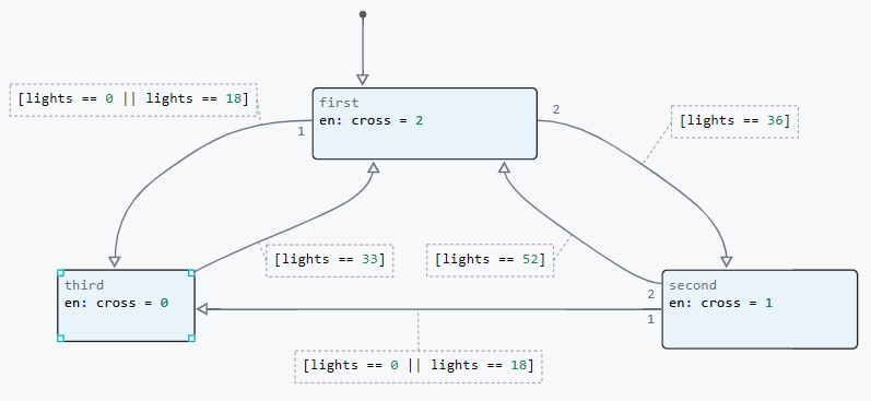
State diagrams
In the block state diagram Common_Counter using the state Counter and transitions 2 and 3 the operation of the incrementing counter is reproduced with a reset after 54 seconds. Condition Service and the transition 1 they are used to reset the counter to the value "-1" when setting the standby mode for the intersection.
.png)
Depending on the value of the counter variable cntr in the block state diagram Traffic_Lights the variable value is selected lights, encoding the status of sections of automobile traffic lights. In this case, all states except ninth and tenth the sequence of switching sections in the operating mode is reproduced.
Block Status diagram Traffic_Lights It is shown in the picture below.
.png)
In turn, depending on the value of the variable lights in the block Crosswalk the variable value is selected cross, encoding the status of a pedestrian traffic light.
Block Status diagram Crosswalk It is shown in the picture below.
.png)
In the settings of each block state diagram Chart signal tables are defined. Initial values of the output variables:
- block
Common_Counter, a variablemode = 0; - block
Traffic_Lights, a variablelight = 33; - block
Crosswalk, a variablecross = 2.
Simulation results
Let's load the described model:
if "arduino_crossroad" in [m.name for m in engee.get_all_models()]
    m = engee.open( "arduino_crossroad" );
else
    m = engee.load( "$(@__DIR__)/arduino_crossroad.engee" );
end

data = engee.run(m);
From the obtained model data, we will plot the counter variables. counter, encoded states of sections of automobile traffic lights traffic_lights and pedestrian traffic lights crosswalk_lights.
using Plots
plotlyjs()
plot(data["counter"].time, data["counter"].value,
    label="Counter", size=(900,300), lw=2, st=:step)
plot!(data["traffic_lights"].time, data["traffic_lights"].value,
    label="Traffic light code", size=(900,300), lw=2, st=:step,
    legend=:topleft)
xlabel!("Time, seconds")
ylabel!("Values")
plot(data["crosswalk_lights"].time, data["crosswalk_lights"].value,
    label="Code pedestrian traffic light", size=(900,300), lw=2, st=:step, color=:green,
    ylims = (0,3), xticks=:none, legend=:topleft )
    xlabel!("Time, seconds")
ylabel!("Values")
The displayed graph shows the change in variables. The calculation period in the model is set to 1 second. Changing the state variables of sections of automobile and pedestrian traffic lights traffic_lights and crosswalk_lights the values and duration correspond to the time chart
Uploading code to Arduino
To transfer the developed model to the target device, we will generate a C code.:
engee.generate_code( "$(@__DIR__)/arduino_crossroad.engee",
                     "$(@__DIR__)/arduino_crossroad_code" )
In the specified directory arduino_crossroad_code the pluggable files were generated. Also in the directory of the demo example arduino_crossroad a pre-written Arduino sketch with the name of this directory has been posted. arduino_crossroad.ino. It connects the header file obtained during code generation, initializes global variables, defines the model calculation cycle, and calls the model calculation functions. A detailed description of the sketch is given in the comments of its code.
To execute the code on Arduino, you need to download the directory arduino_crossroad and upload the sketch arduino_crossroad.ino from the Arduino IDE to the target device.
Code execution on Arduino
After successful compilation and uploading of the sketch to the target device, signals will be generated at the digital outputs of the debugging board to turn on the traffic light sections (LEDs on the breadboard). In order to make sure that the model is working correctly, open the serial port monitor in the Arduino IDE.
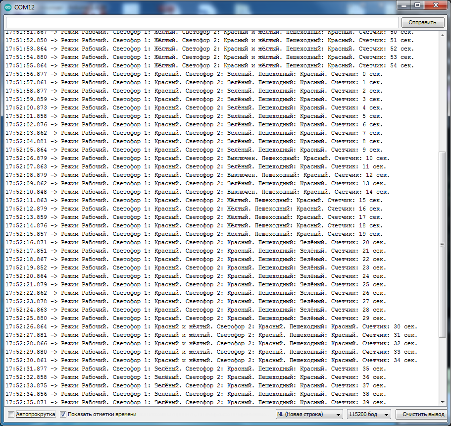
It can be seen that the data specified in the block is output to the serial port. To Serial messages in the required format with a frequency of 1 second.
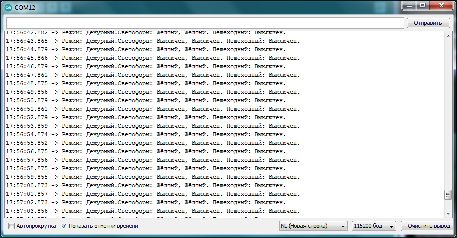
When the push-button contact is pressed, the intersection traffic lights switch to standby mode, and the following messages are output to the serial port:
.png)
The required message is output to the serial port with a frequency of 1 second. Therefore, the operation of the intersection in standby mode is also correct, which confirms the operability of the model and code.
Conclusion
In this demo, a model of an intersection with two three-section automobile and one two-section pedestrian traffic lights for Arduino-compatible platforms was developed. The control algorithm is recreated using the library of finite automata. The model reproduces the operation of a traffic light in two modes, while ensuring not only switching sections, but also their flashing. The algorithm's performance was tested on the target device, and the resulting code not only controls the LED sections, but also transmits messages to the serial port about the current mode, the illuminated sections of the three traffic lights, and the current operating time.